Volvo 850 Rear Speaker Crossover Capacitor Replacement

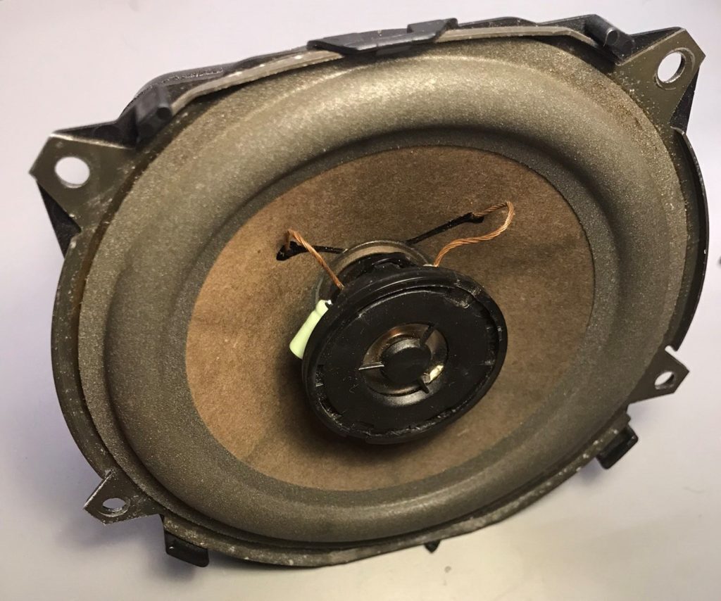
If you are missing treble or have popping or rattling in the rear door speaker, chances are the crossover capacitor for the tweeter has failed.
Time:

Approx. 10 minutes a speaker

What you’ll need:

  • Capacitor
  • Hot Glue Gun

-Capacitor

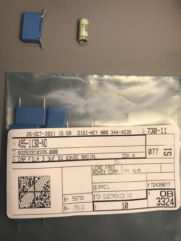
Suggested Replacement (PET Film)
3.3uF ±5% 63V AEC-Q200 [15mm lead spacing] B32522C0335J000


Preparation

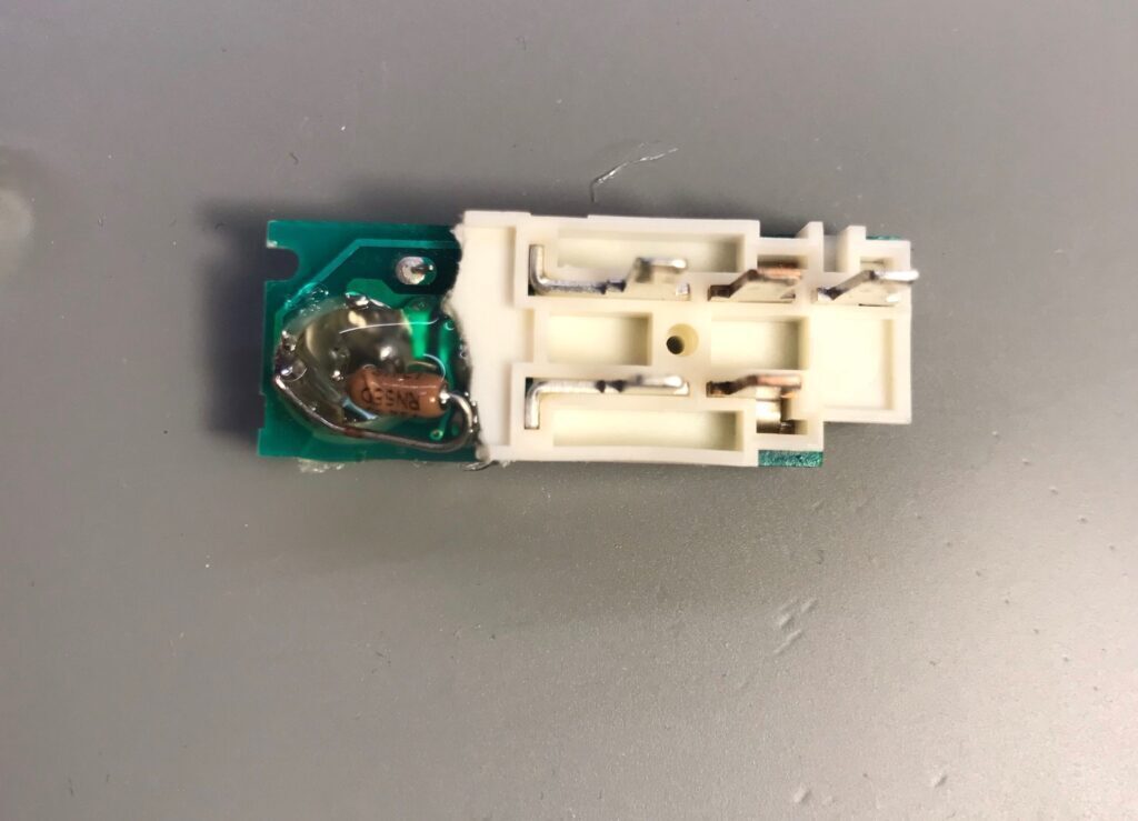
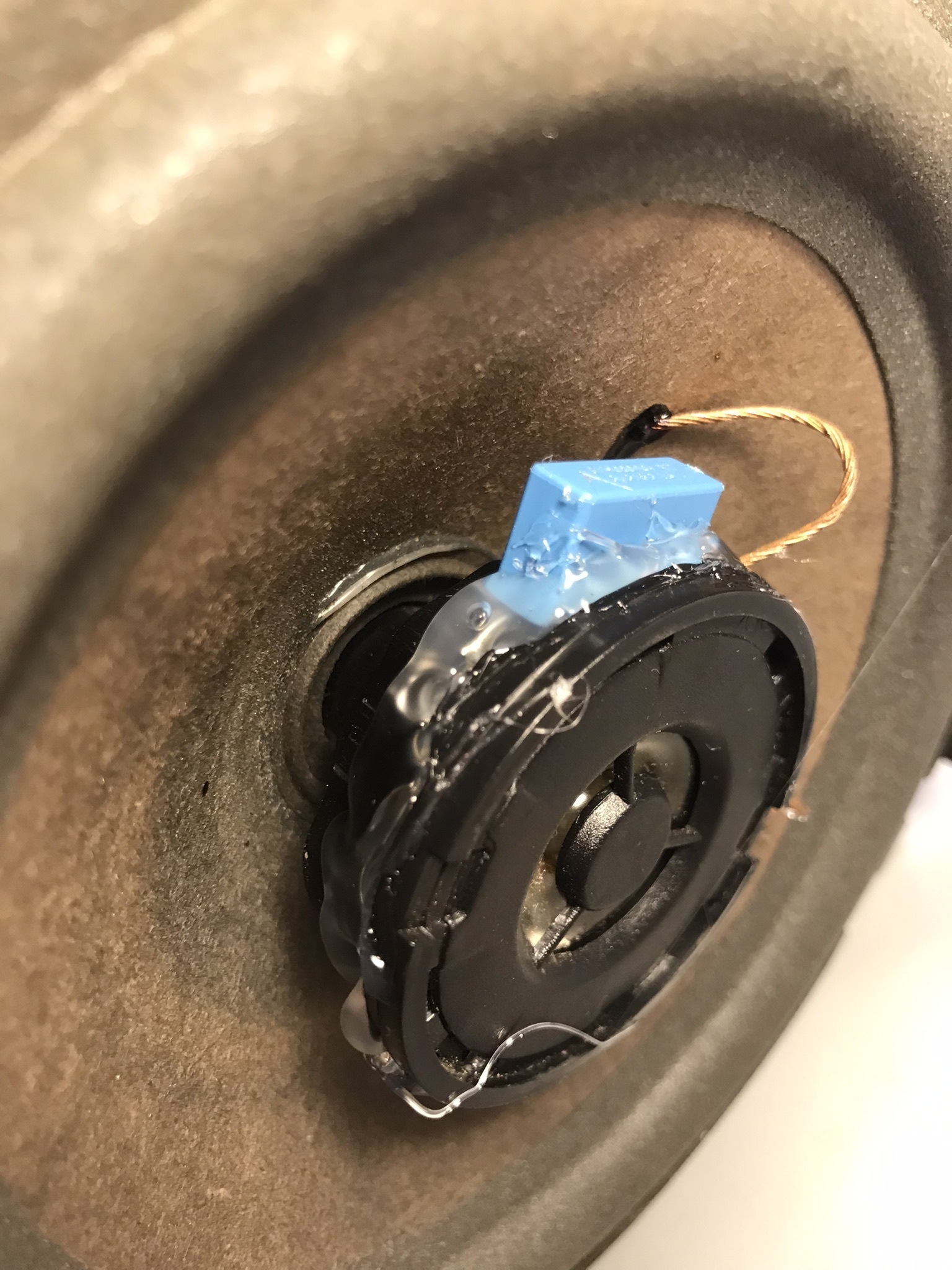
The First step is to cut out the old capacitor. Be careful doing this and make sure to leave as much of the existing leads as possible.

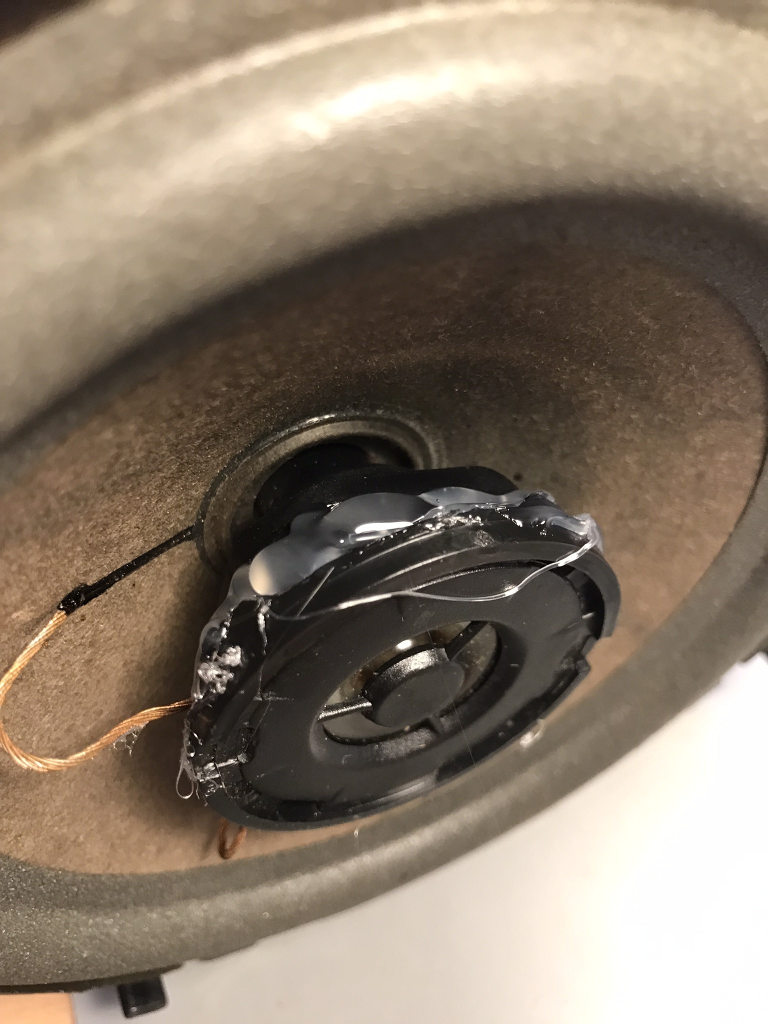
After removing the rear speakers, in some cases the plastic holding the tweeter may appear cracked or the plastic may begin to crack after reaching a tool in to cut the old capacitor out; later on we will reinforce these cracks with hot glue.
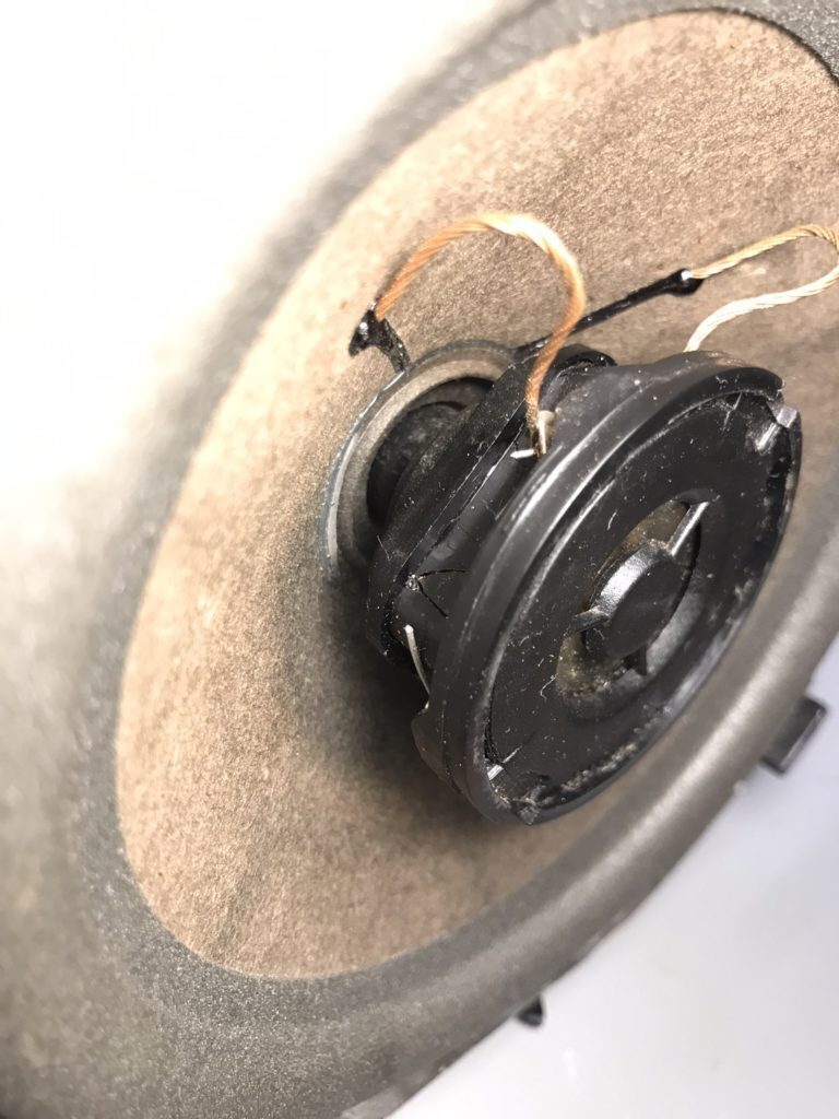
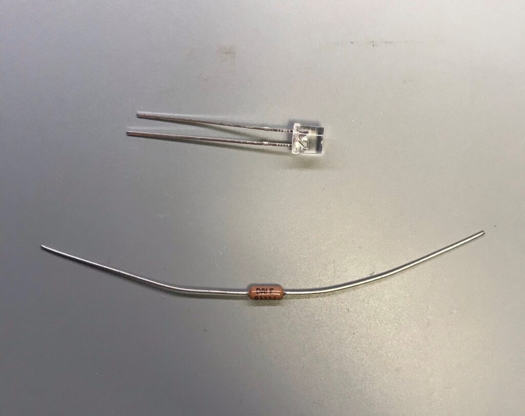
Now after selecting the new capacitor the pins need to be bent so that they can be soldered onto the existing leads of the tweeter.
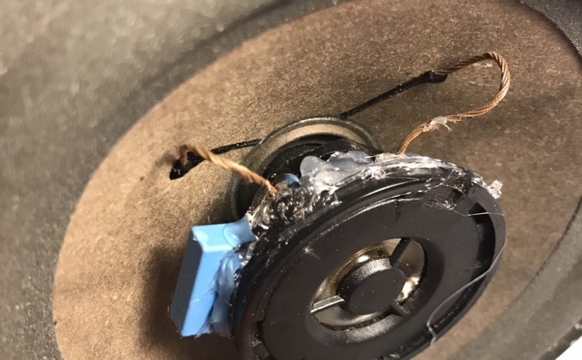
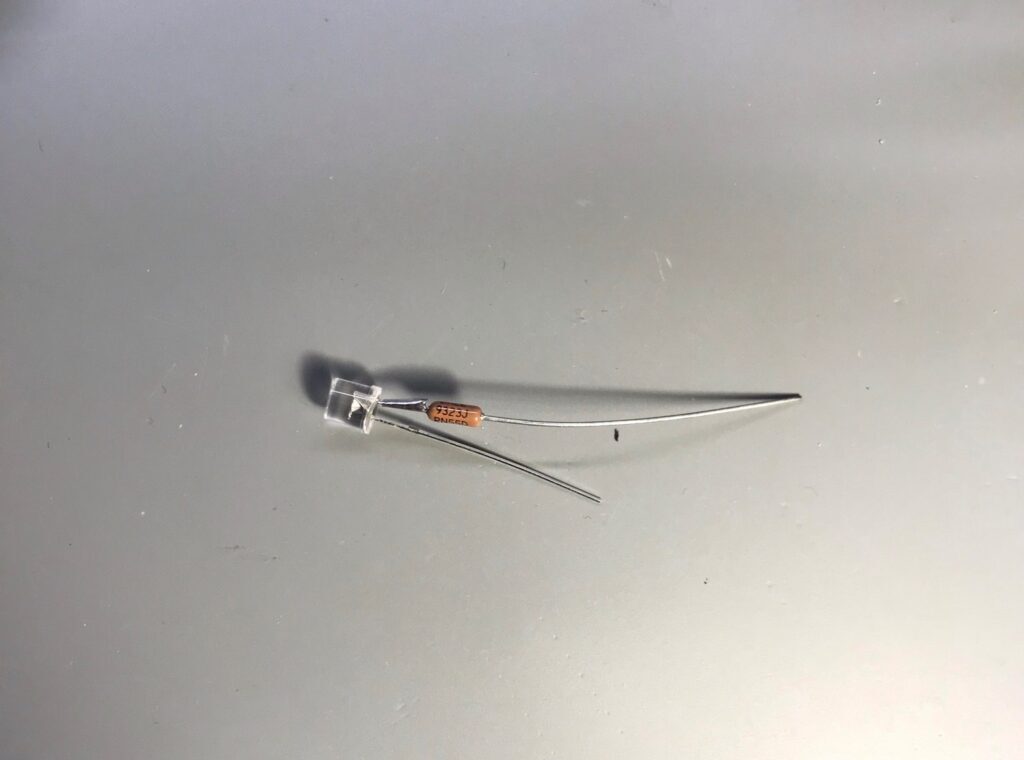
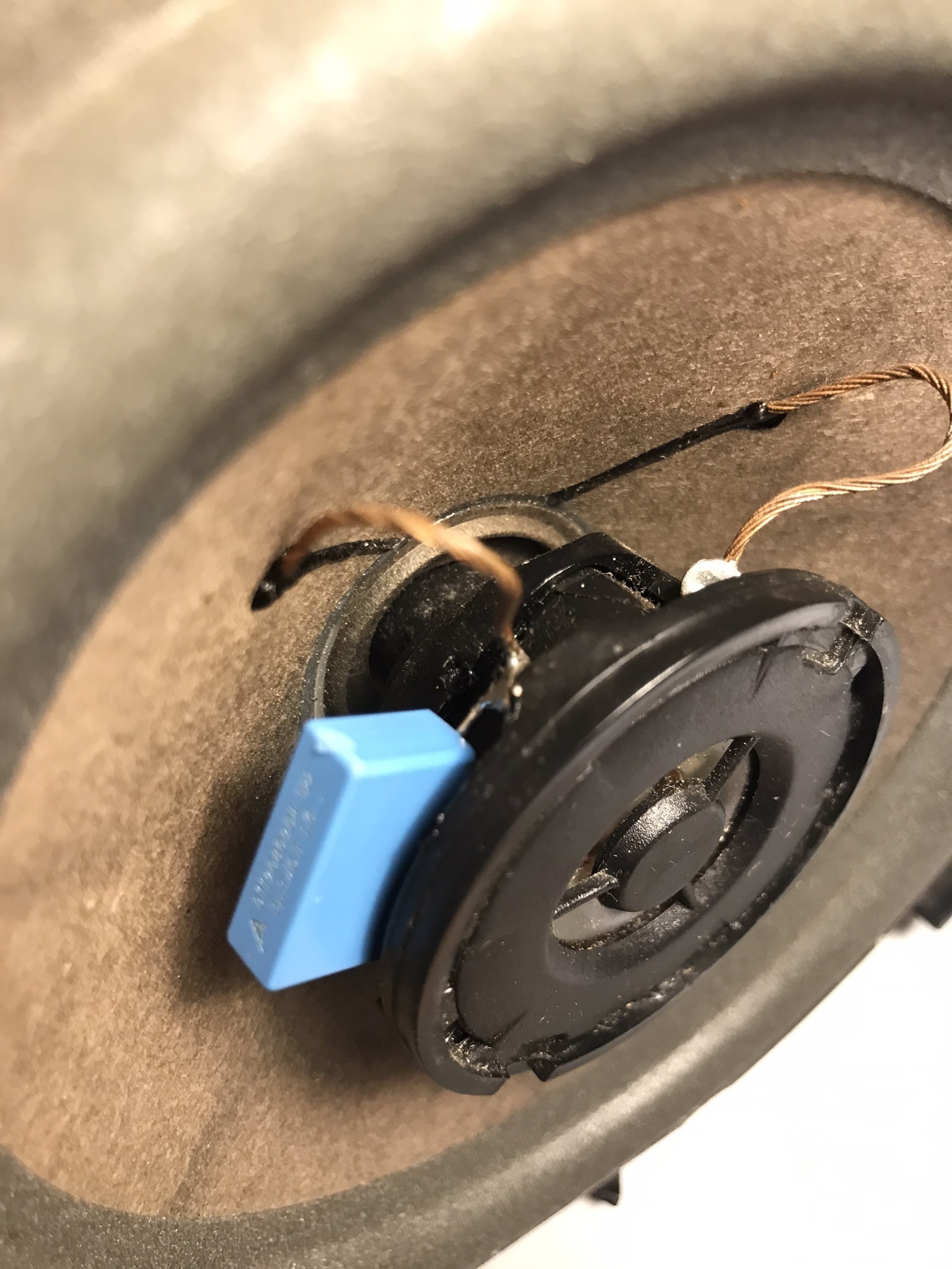
At this point, I tried holding the capacitor with helping hands but that did not allow enough room to get the soldering iron in. I found it best to hold the capacitor with my left hand and the soldering iron with my right hand. I simply tacked one of the leads (left photo) then moved on to the other lead. After the capacitor was in place, I cleaned up the solder.
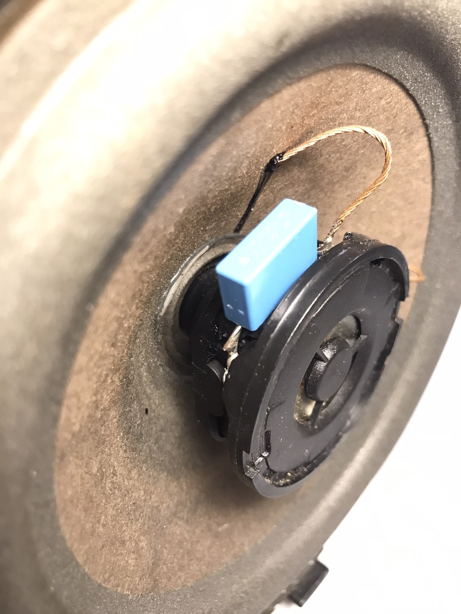
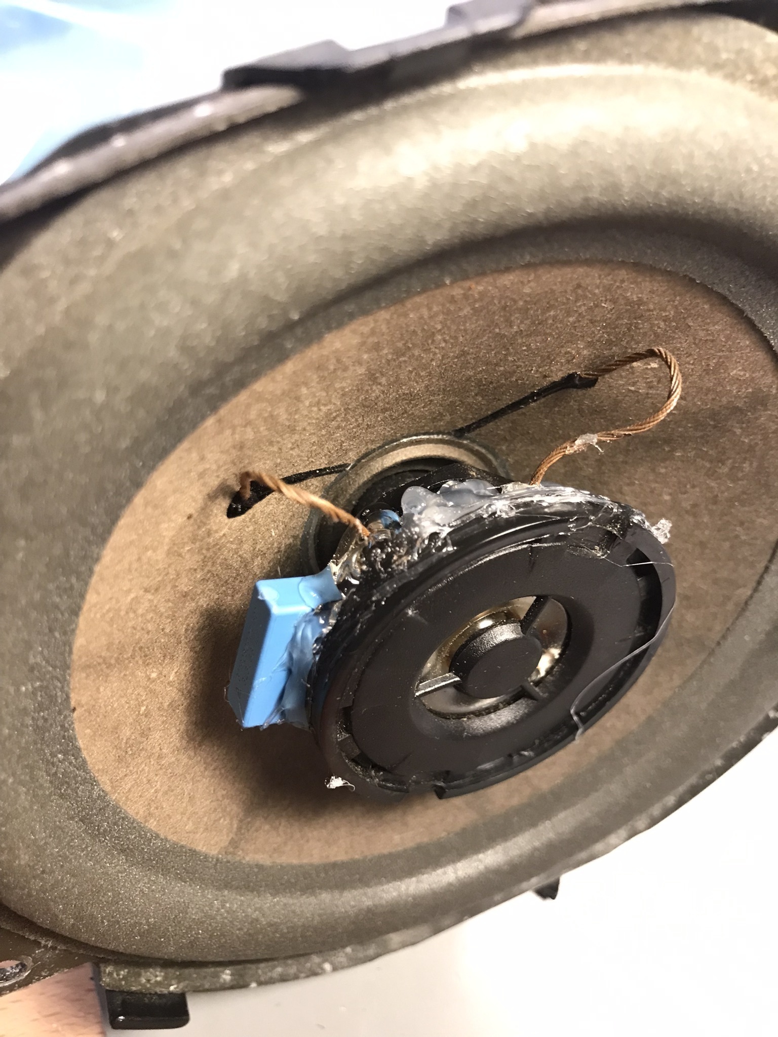
Lastly, I hot glued all around the tweeter housing. I also glued in the capacitor and its soldered leads to protect them from vibration.
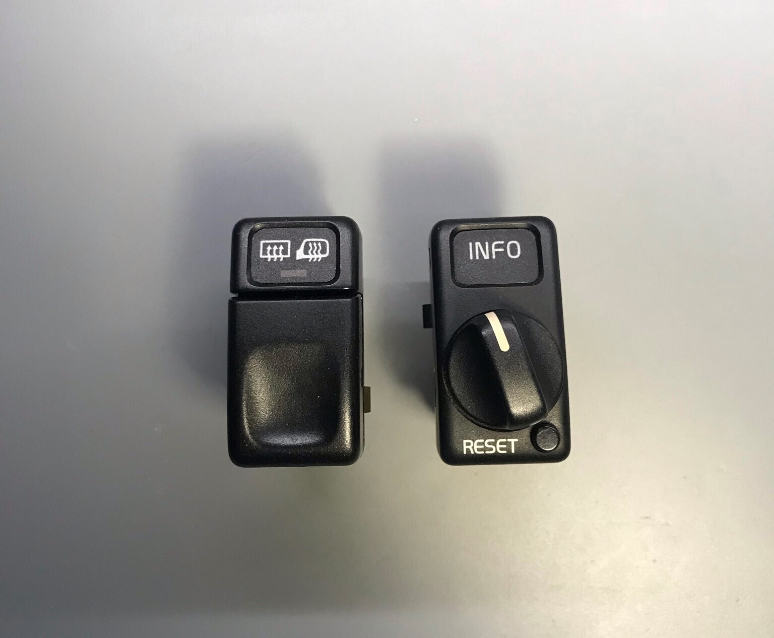
Volvo 850 Switch Illumination LED Conversion

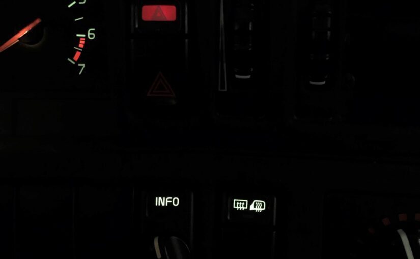
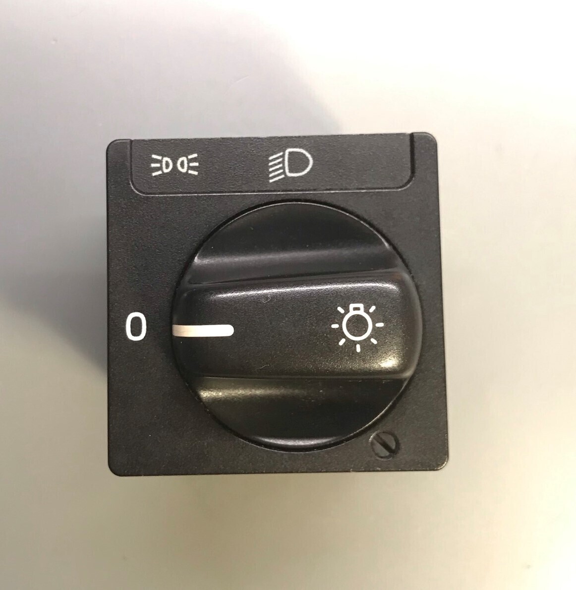
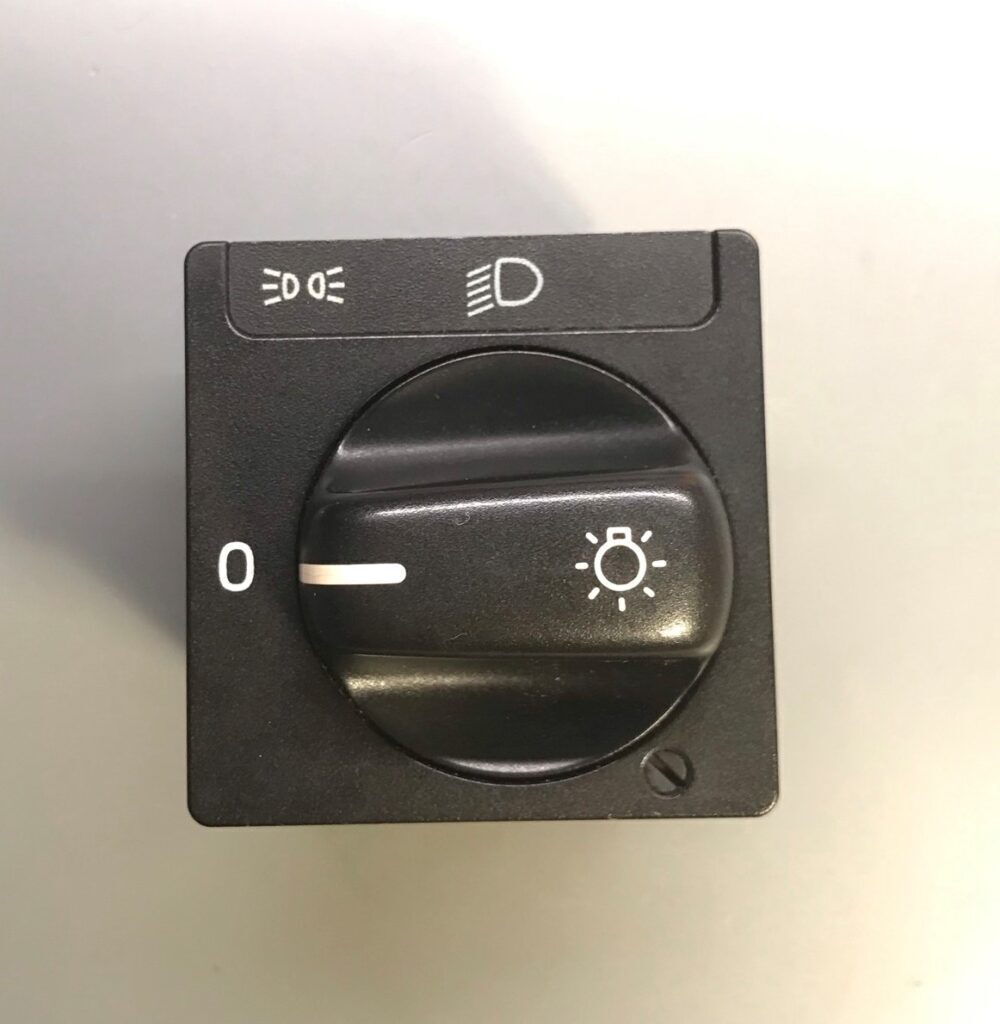
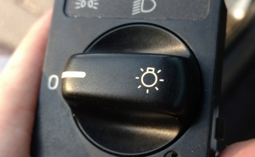
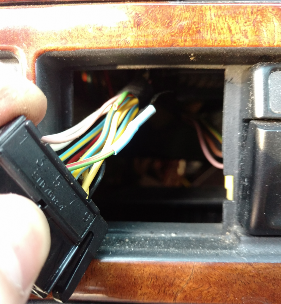
This tutorial shows how to replace the incandescent bulbs inside Volvo 850 switches with LEDs. This is applicable for all normal switches, the info switch, and the headlight switch.

Time:

Approx. 10 minutes a switch

What you’ll need:

  • Jewelers flat blade screwdrivers (the more the better)
  • Warm white LED (5mm, Flat)
  • Resistor (1.24K Ω) 1/4 watt [Calculated below for match]
  • Hot Glue Gun
  • Dielectric Grease (optional)
  • Helping Hands Soldering Aid (optional)

LED specs

EDGELEC 100pcs 5mm Warm White LED Lights Emitting Diodes DC 3V Flat Lens 29mm Lead Frame + 100pcs Resistors (for DC 6-12V) Included, Bright Bulb Lamp

Product Features: Warm White Lights / 5mm Flat Clear Lens Lens / 29mm Long Lead / DC 3.0V-3.2V (IF=20mA) / 0.06 Watts / Wavelength 2000K-3500K / 60° Viewing Angle

– Choosing a resistor value

This step involves powering a non-LED converted switch on the bench from 12V and using another switch with the bulb removed from it so you can poke a LED through the back of it.

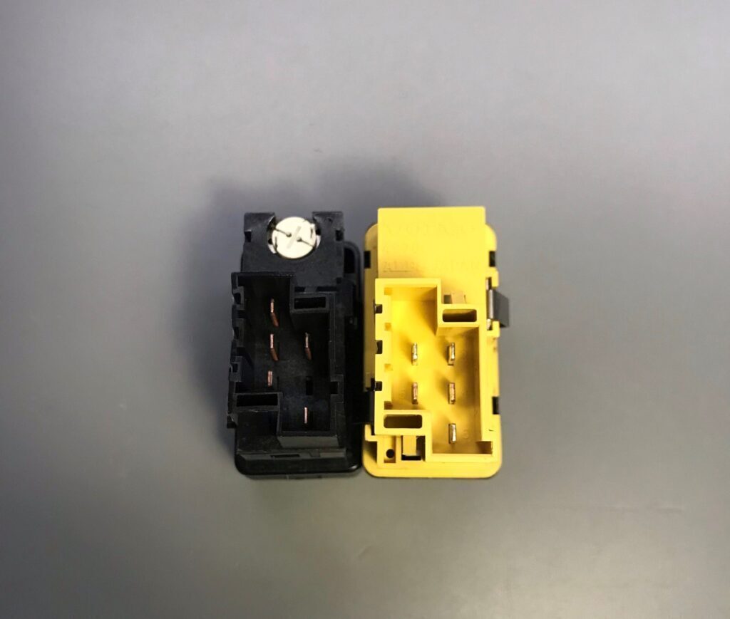
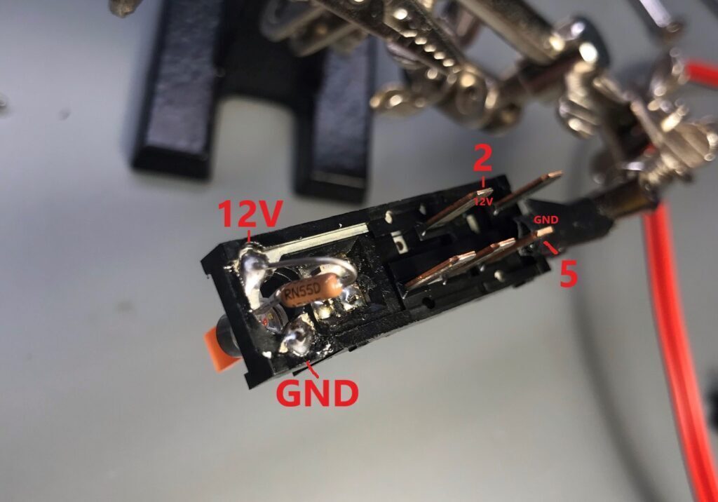
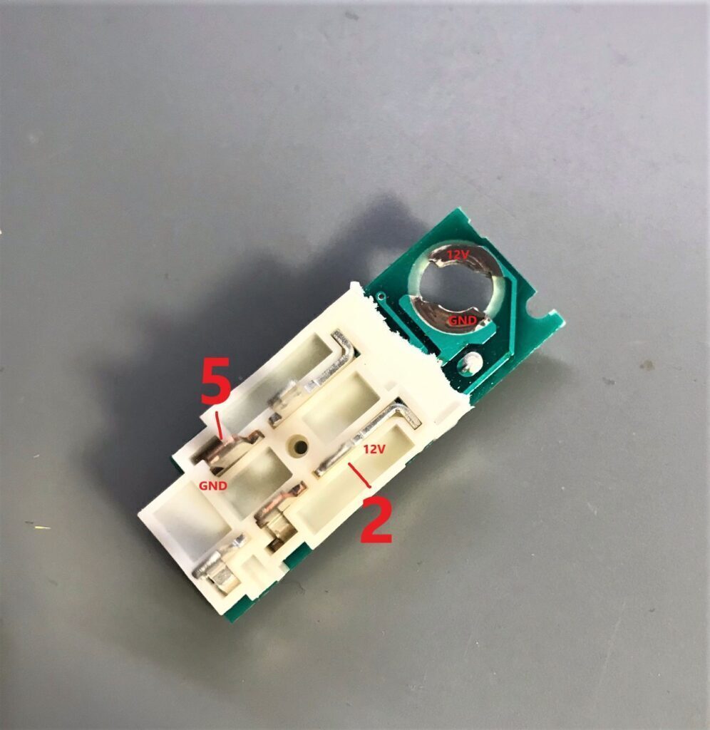
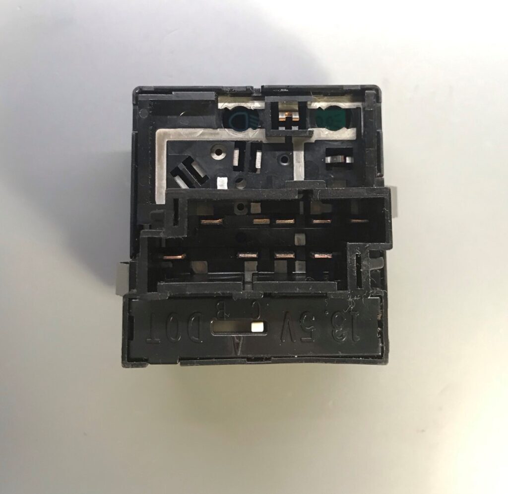
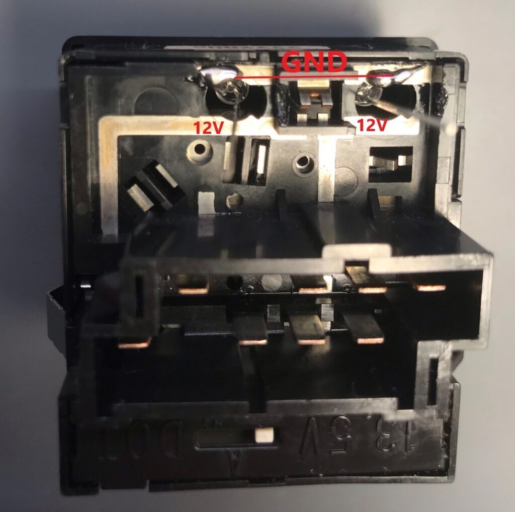
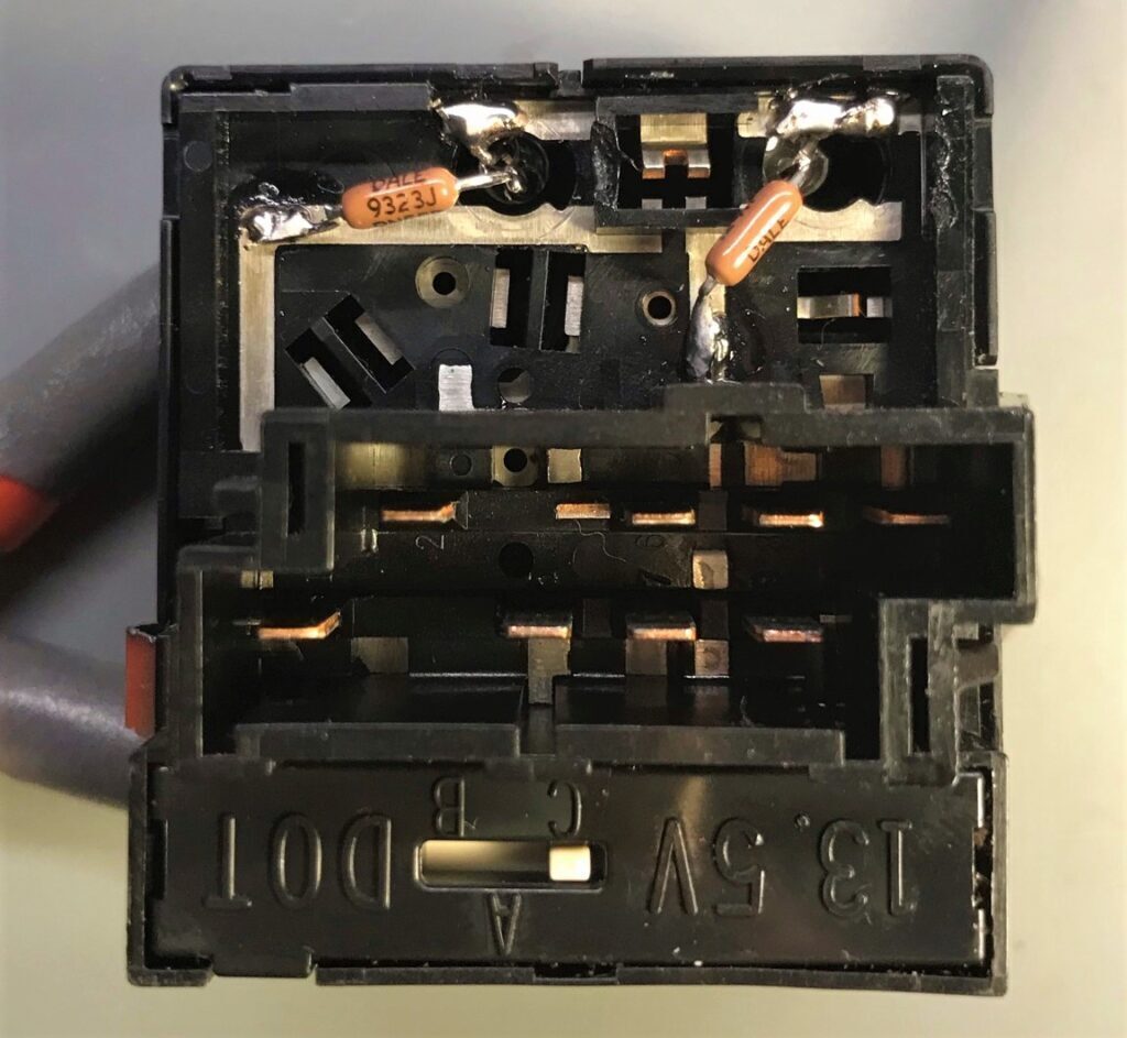
Pin 2 on the switch is 12V and Pin 5 is GND. These pin numbers are written next to the pins on the back of the switch.

Hook the LED up to a constant current power supply set at 12V so that you can dial in the appropriate current level so the LEDs match the lamps in the rest of the car. Make sure not to violate the maximum current of the LED!

Now with the LED on, take down the voltage that you read on the power supply (this is your LED forward voltage).

[ 12V – (LED FORWARD VOLTAGE) ] / Current (A) = Resistance (Ω)

For this tutorial, I will be using 1.24K Ω as a resistor value.


Preparation

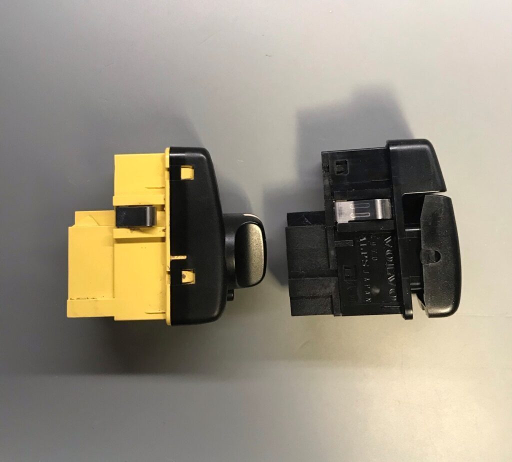
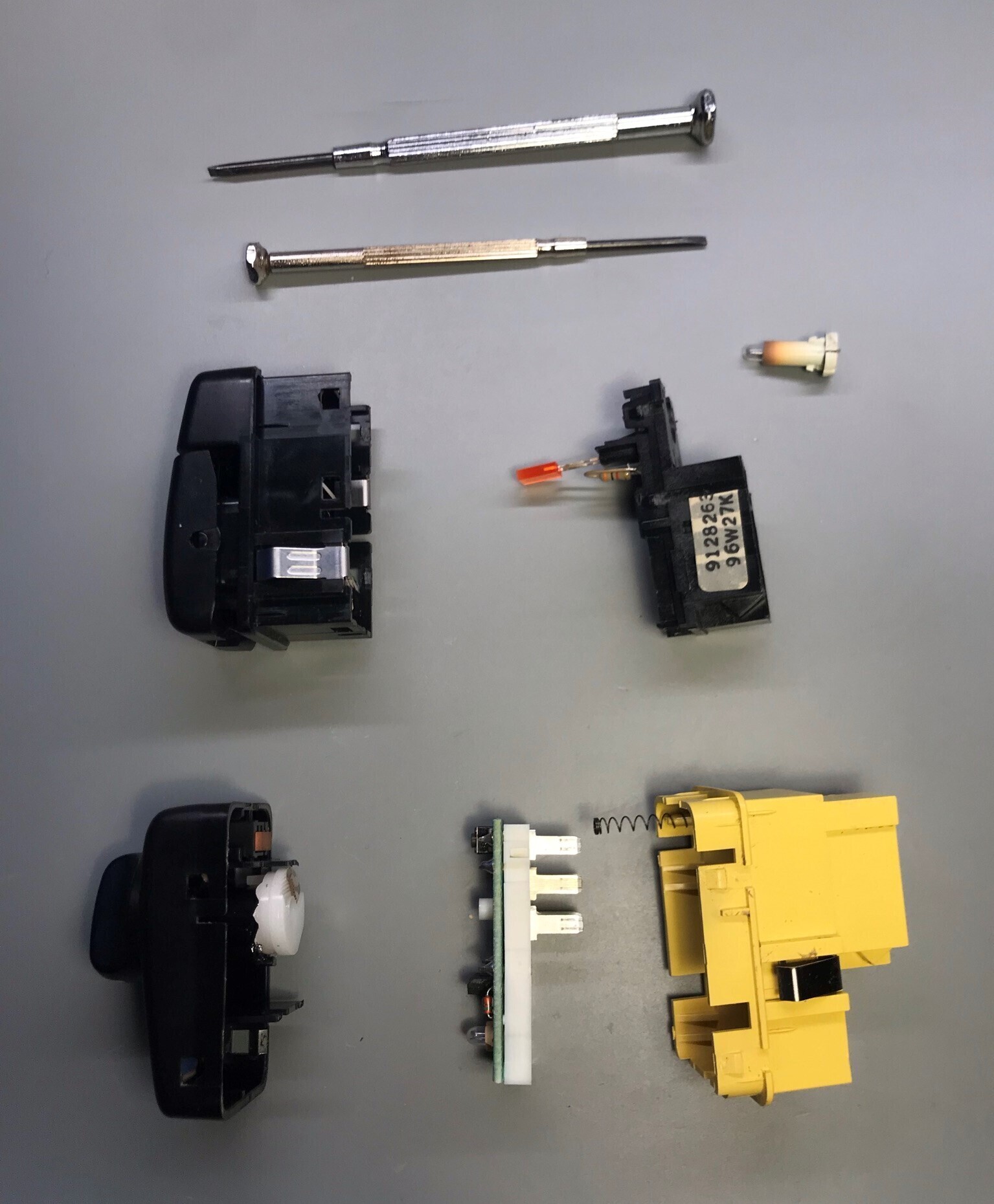
Start by opening up the switch by prying the tabs on all corners of the switch carefully and separating the face switch from the body (not necessary for headlight switch).

For the regular style switches it may be easier to solder the resistor to one leg of the LED (anode or positive side is used for this tutorial). Keep track which side of the LED has a flat spot on it (this is the negative side of the LED).

Regular Switch

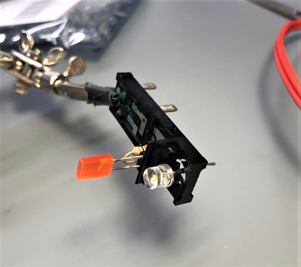
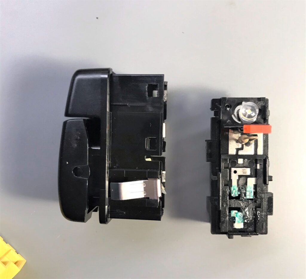
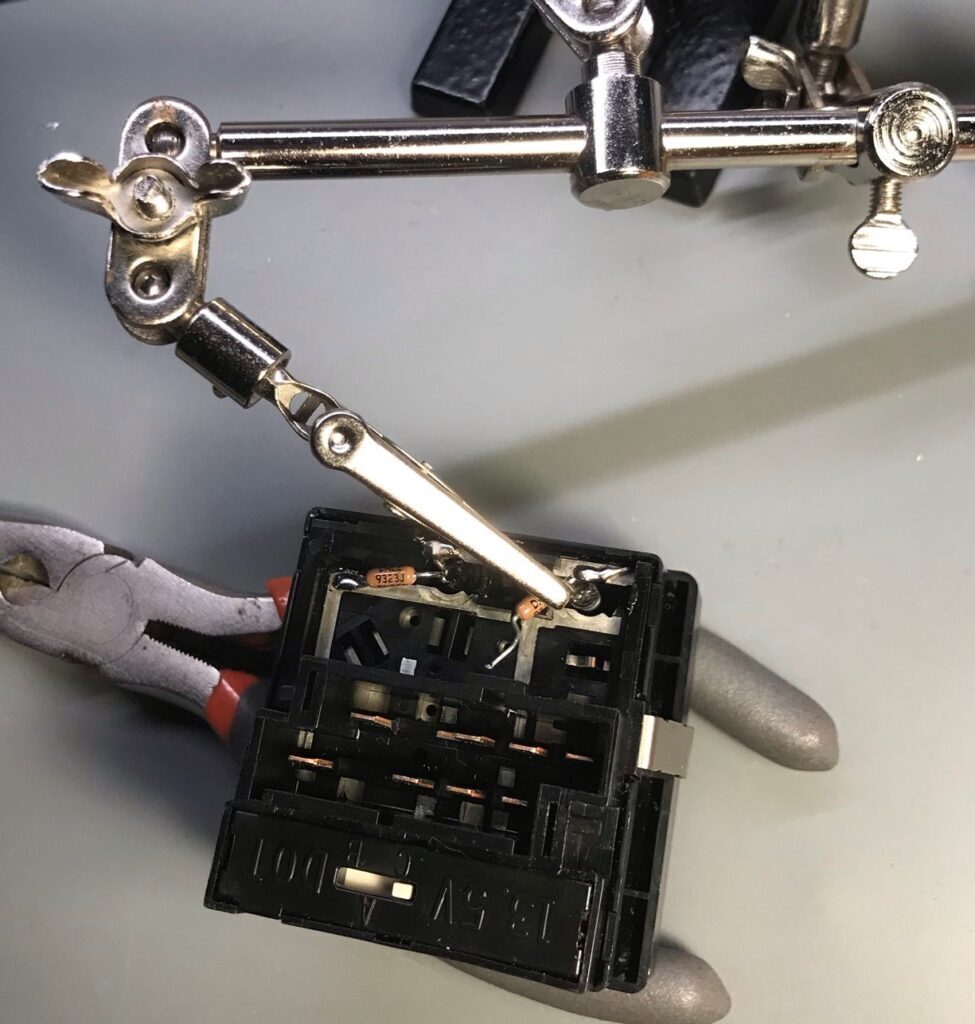
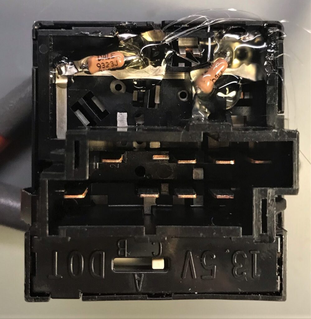
Insert the LED into the switch. All you need to do is get the LED to be roughly aimed forward. The leg without the resistor can be soldered through a hole in the switch. The resistor can go through the “bulb hole”. Make sure the LED polarity matches the pictures below or there will be no light. You also want to make sure the resistor and LED leads don’t short out with how they are situated.

Now you can optionally clean the contacts and apply a dab of dielectric grease to protect the contacts before snapping the switch back together.

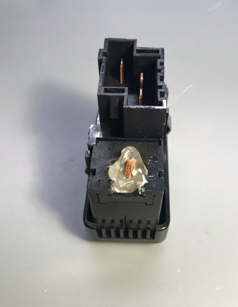
At this point the resistor is still hanging out the back. The simplest solution is to use some hot glue deep in the bulb hole to keep the LED and LED leads from moving. You can also use it to coat any bit of the resistor or resistor leads still sticking out the back.

Info Switch

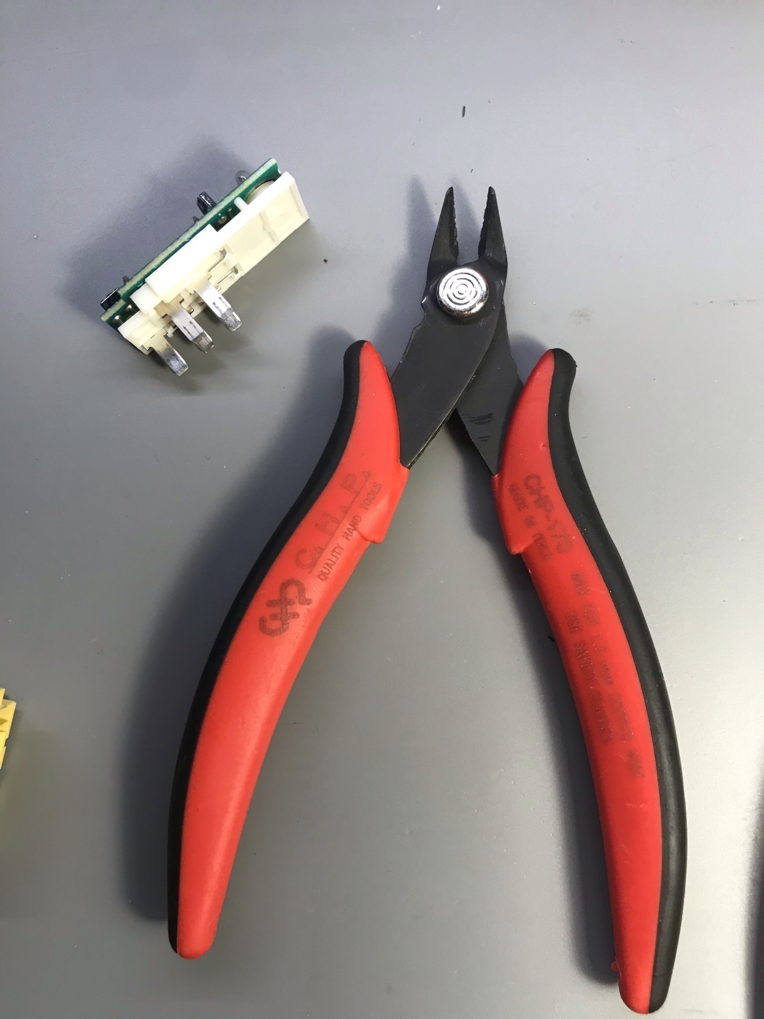
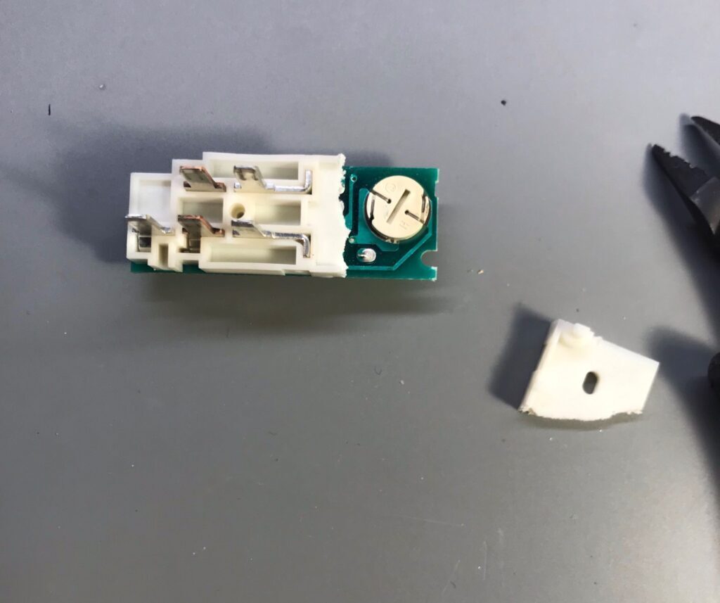
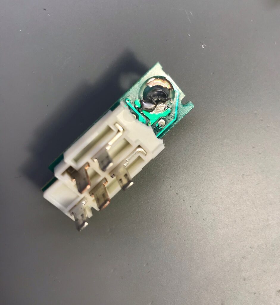
Once you get the switch open, to access the bulb, you must cut a bit of the white backing plastic.

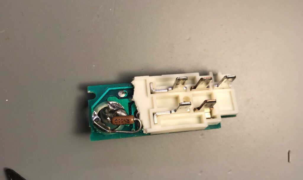
I found it easier to solder the negative lead of the LED to the GND pad of the switch before soldering the resistor to the 12V leg.

You basically orient the LED as shown below. You may need to chop off a bit more white plastic. Make sure not to accidentally short any leads out.

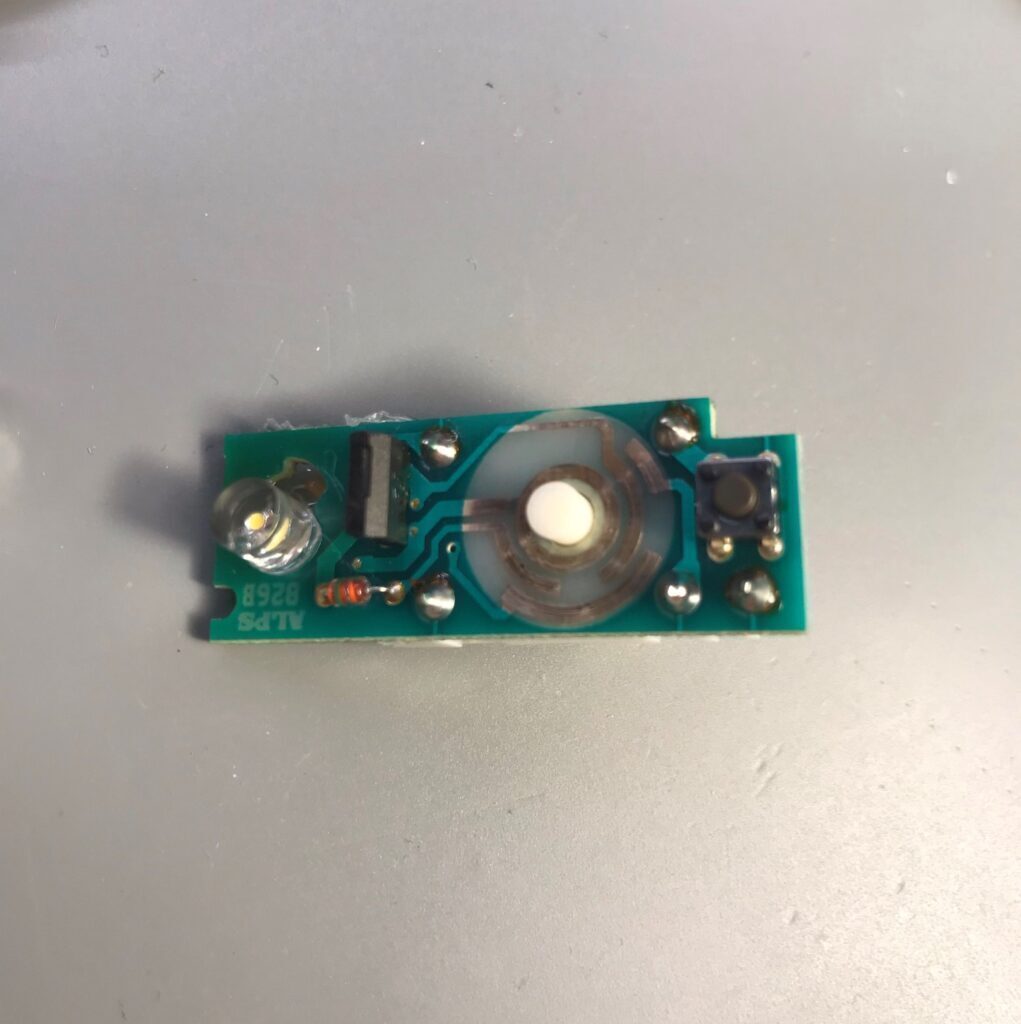
The last step is to encase the LED and leads in hot glue. You can now optionally clean the tracks for the info switch on the front side of the PCB before reassembly.

Headlight Switch

It is not necessary to open the headlight switch to install LEDs.

It was easy to use some helping hands to hold one leg of the LED to help solder the other bent leg of the LED. The LED cathode is soldered to the GND side.

You can use some helping hands to help hold the resistors for soldering.

Make sure none of the leads are shorted. As a final step. I coat the back of the LED and resistor to avoid accidental shorts and vibration.
Volvo 850 Electric Climate Control Illumination LED Conversion

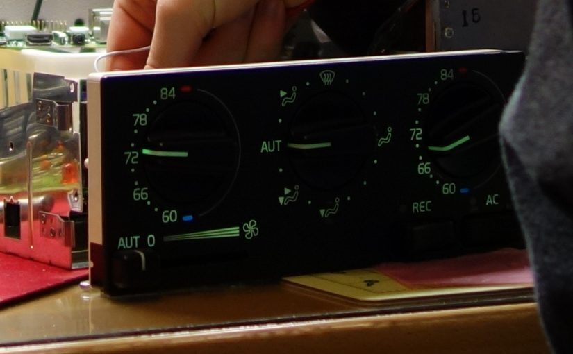
If you own a Volvo 850, sooner or later the bulbs in your Electric Climate Control unit will fail. This is very common as Incandescent bulbs are more susceptible to failure than LEDs; the filament can break from vibration or age. This tutorial will cover how to remove your ECC unit, how to replace the bulbs, and how to test your ECC unit on the bench.

Time
Approx. 30 minutes

Parts & Tools 
3x   Warm White 74 LEDs (warm matches the look of the bulbs)
1x   Phillips Screw Driver
1x   12 Volt Power Source with alligator clips (for bench testing the LEDs)

Step 1: Remove Climate Control unit

To remove the climate control unit the radio must be removed. First pop out the 2 tabs on each side.

MAKE SURE YOU CAN FIND YOUR RADIO CODE BEFORE DISCONNECTING THE POWER TO YOUR RADIO OR IT WILL NOT WORK

Then pull the radio out and disconnect the connectors plugged into the rear.

Pull the climate control unit out (It just slides out) the front and disconnect the 3 connectors on the rear.

Step 2: Expose the main circuit board

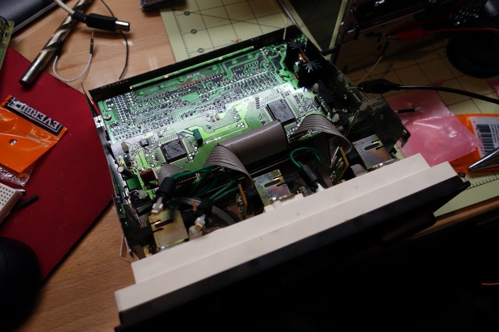
volvoccmainboard

Remove all of the screws on the case and pull up to expose the main circuit board.

Step 3: Find test points

An LED or Light Emitting Diode only allows current to flow in one direction. If you hook an LED in reverse it will not light.
volvocccasegnd

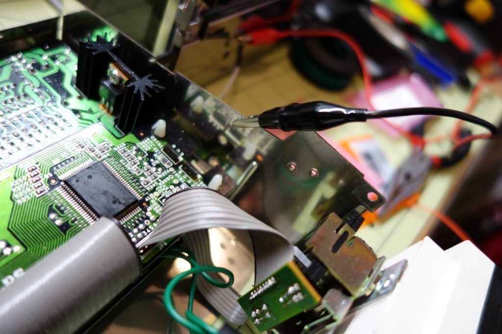
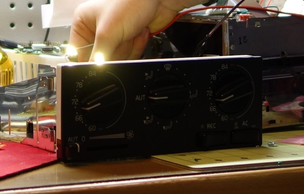
In order to test the LEDs to verify that they are plugged in correctly we will need to power the climate control as if it was in the car. We can assume the case is grounded, but we need to find the 12 Volt connection point to power the LEDs.

volvoccilluminationtest

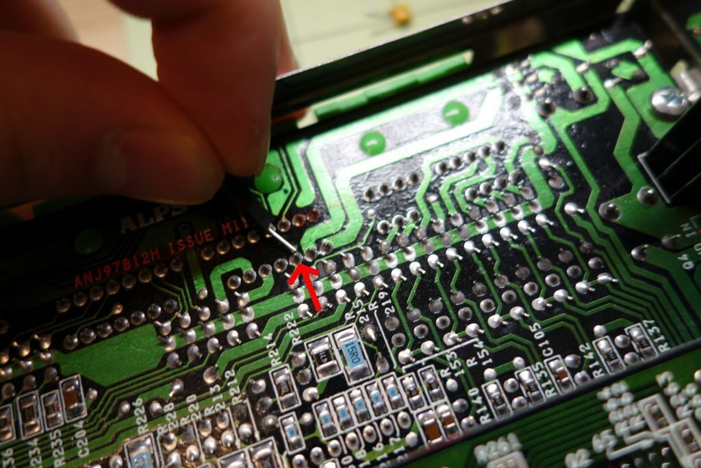
I was able to locate a test point on the board where the night illumination signal comes in from the connector on the rear by tracing a schematic for the wiring to the climate control unit. I suggest marking the pin after you have found it for sure by scoring the solder mask slightly with a paper clip.

Step 4: Test the lights

Verify that the negative end of the power supply is connected to the case. Then power up the power supply and set it to 12 Volts DC. Tap the positive end to the test point and the bulbs should illuminate.

BE VERY CAREFUL NOT TO TOUCH THE OTHER PINS. AND TO ONLY USE 12 VOLTS NOTHING MORE. YOU CAN DESTROY YOUR CLIMATE CONTROL UNIT

Step 5: Swap out one bulb at a time with and LED and test

volvoccleds

I prefer to start with the failed bulb first.

volvoccledsreplaced

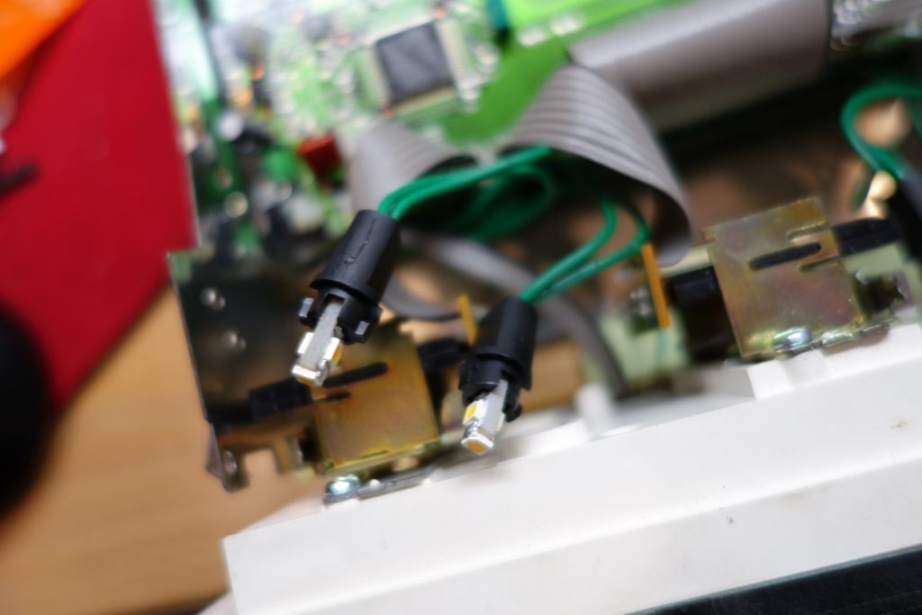
Twist the bulb holder and pull out. Replace the bulb with an LED, and if it does not illuminate, flip the bulb 180 degrees. Make sure the new LEDs are contacting the pins of the bulb holder well.

Repeat this process until all bulbs are changed.

Step 6: Reassemble

volvoccfinaltest

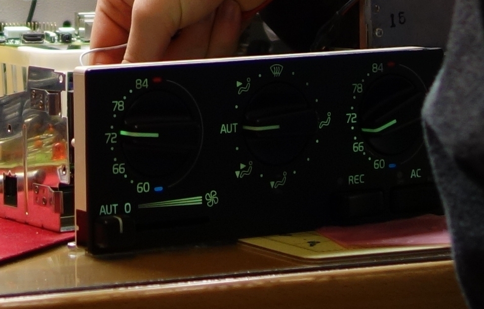
Once everything is working correctly you can reassemble and replace the unit back into the car!