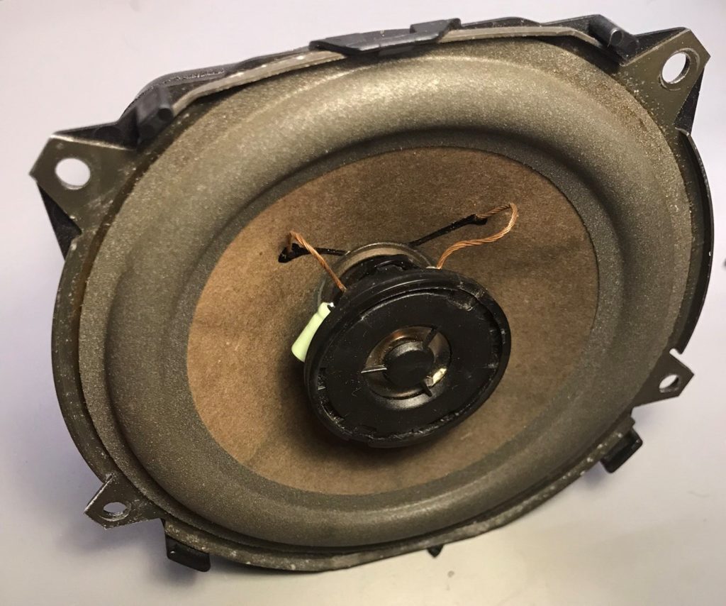
If you are missing treble or have popping or rattling in the rear door speaker, chances are the crossover capacitor for the tweeter has failed.
Time:
Approx. 10 minutes a speaker
What you’ll need:
- Capacitor
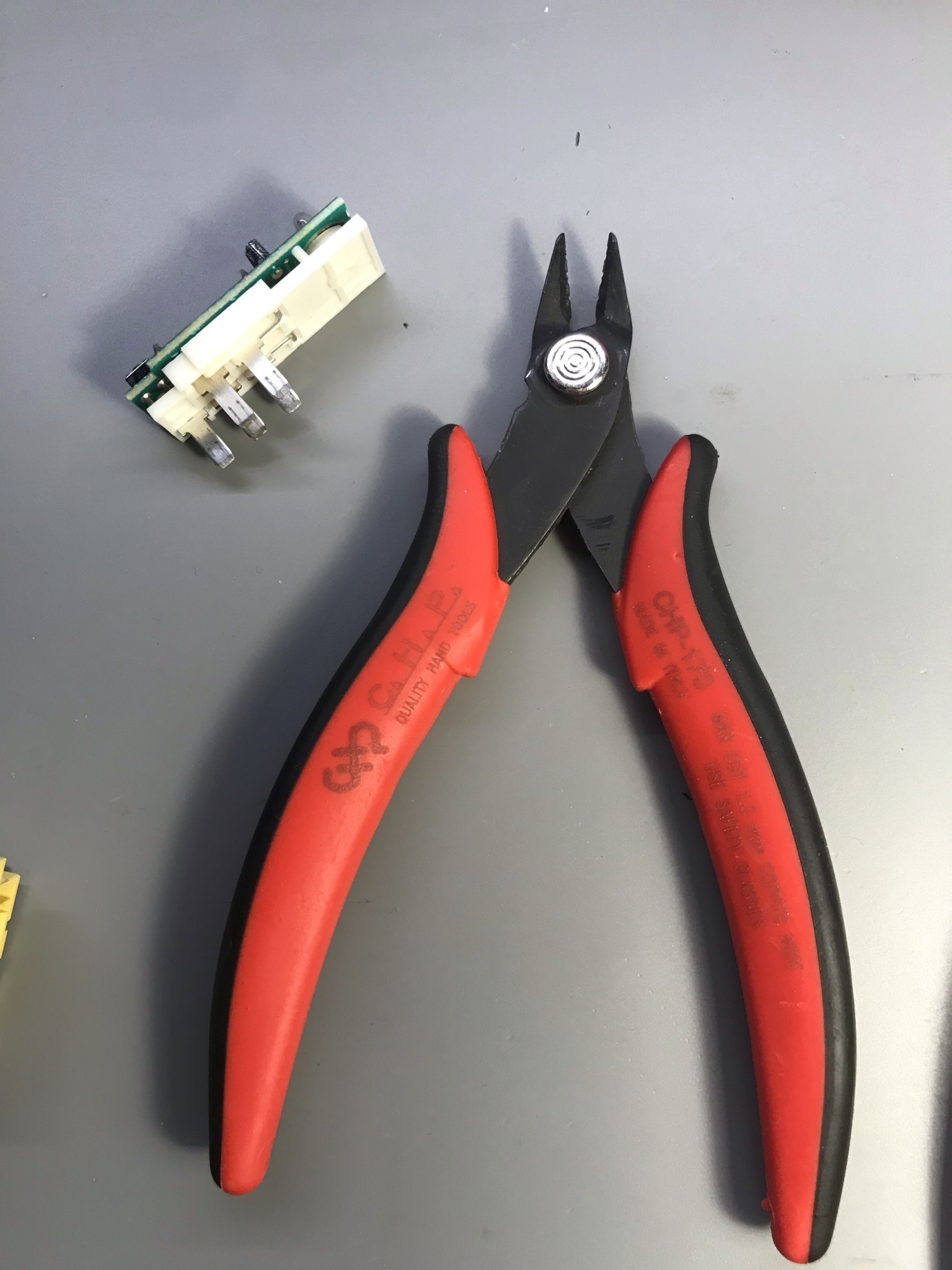
- Hot Glue Gun
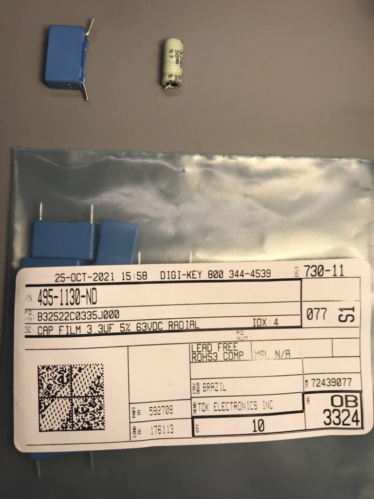
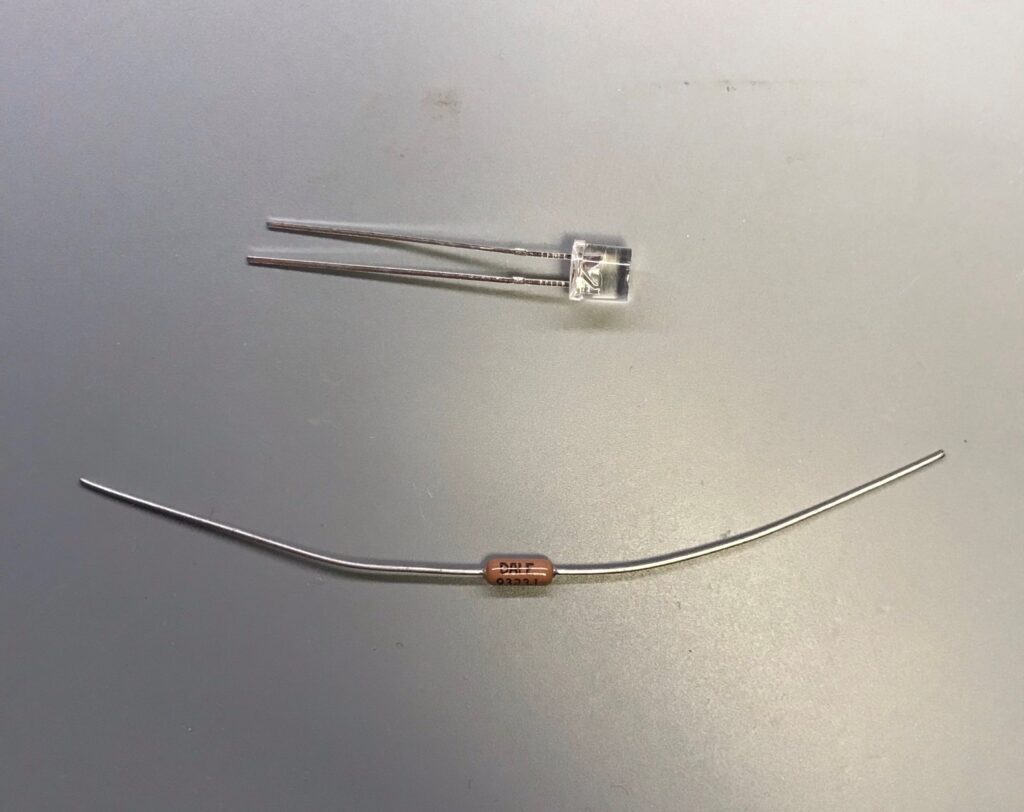
-Capacitor
Suggested Replacement (PET Film)
3.3uF ±5% 63V AEC-Q200 [15mm lead spacing] B32522C0335J000
Preparation
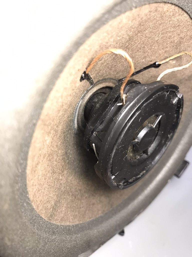
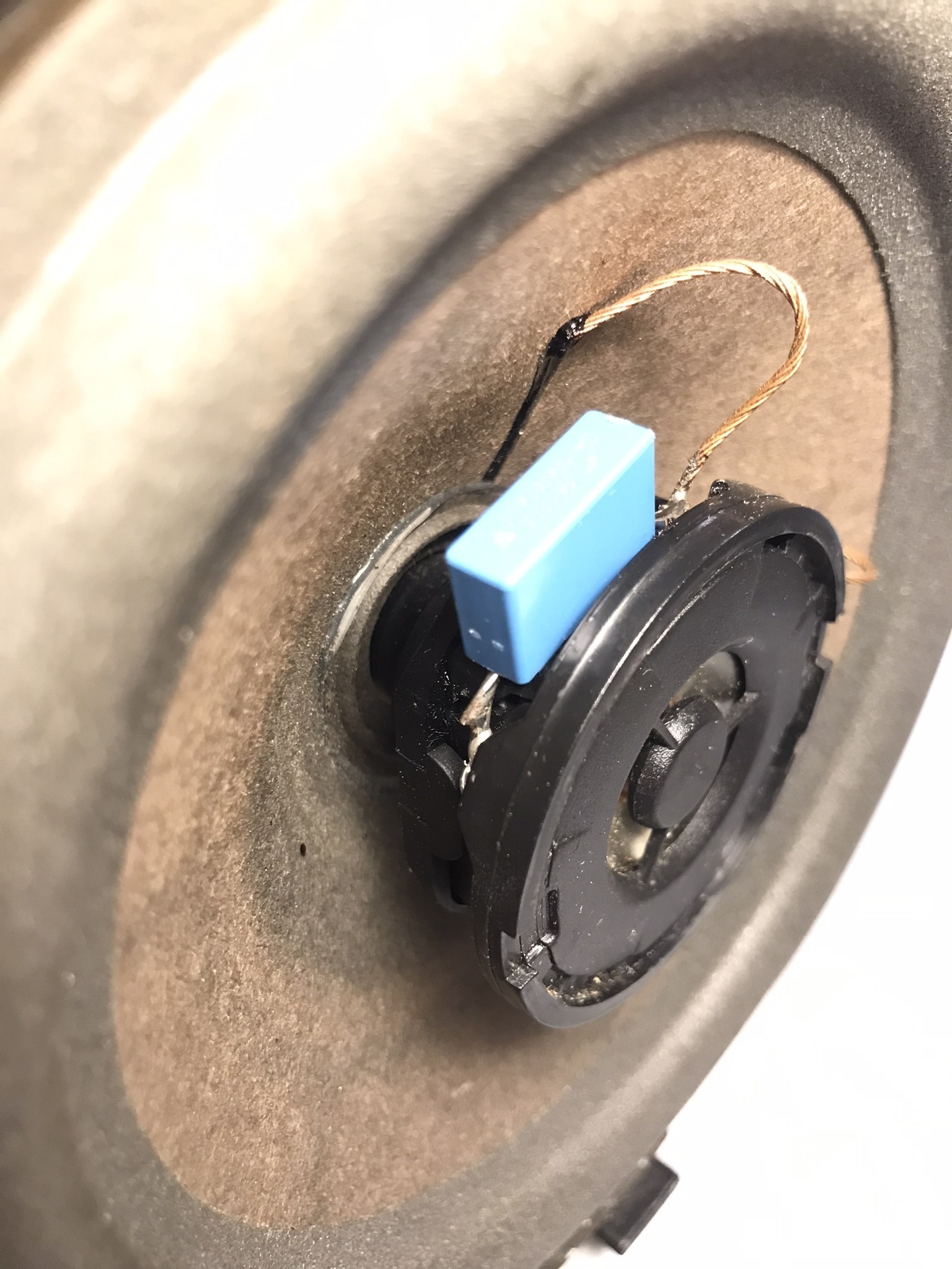
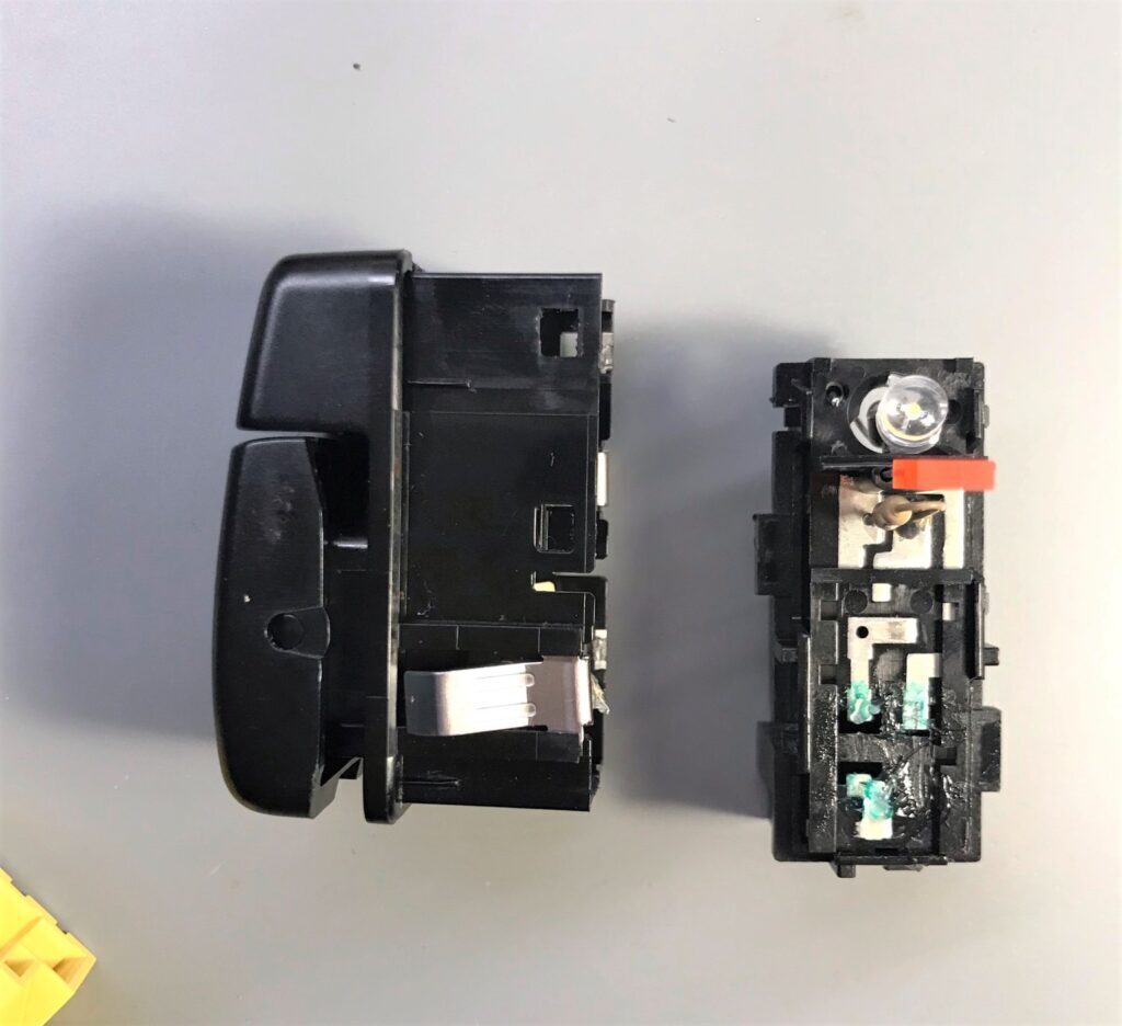
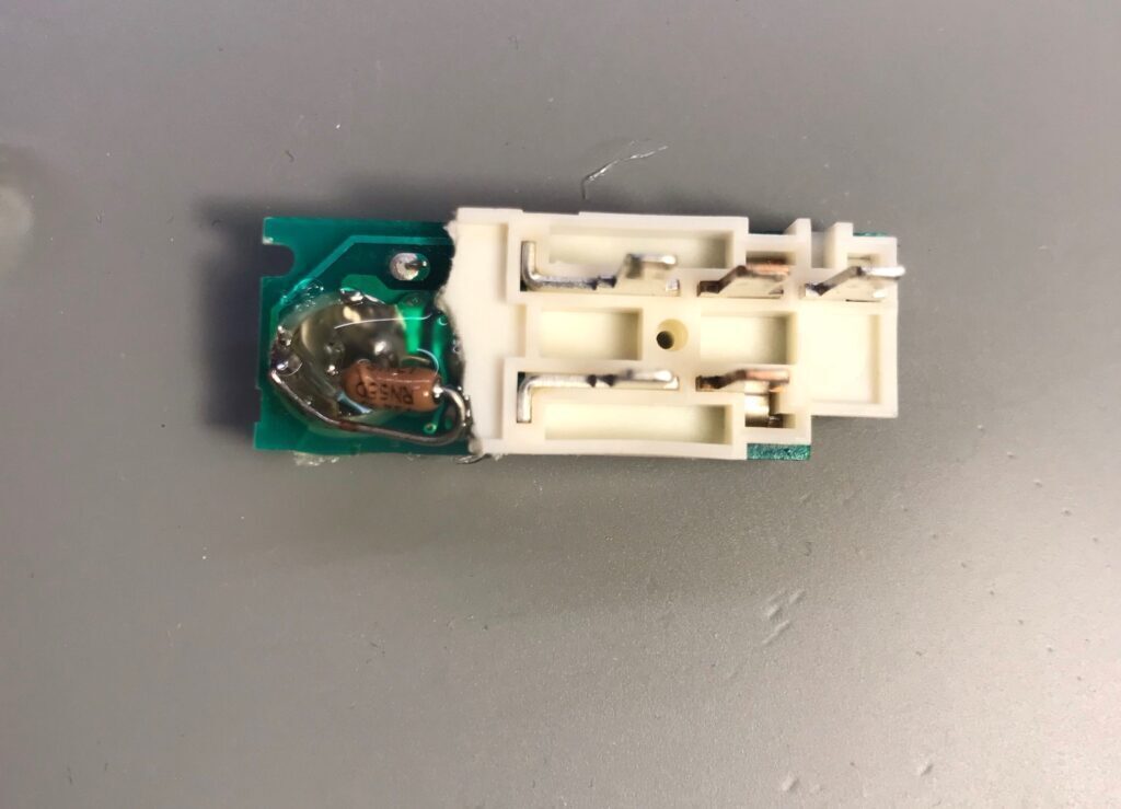
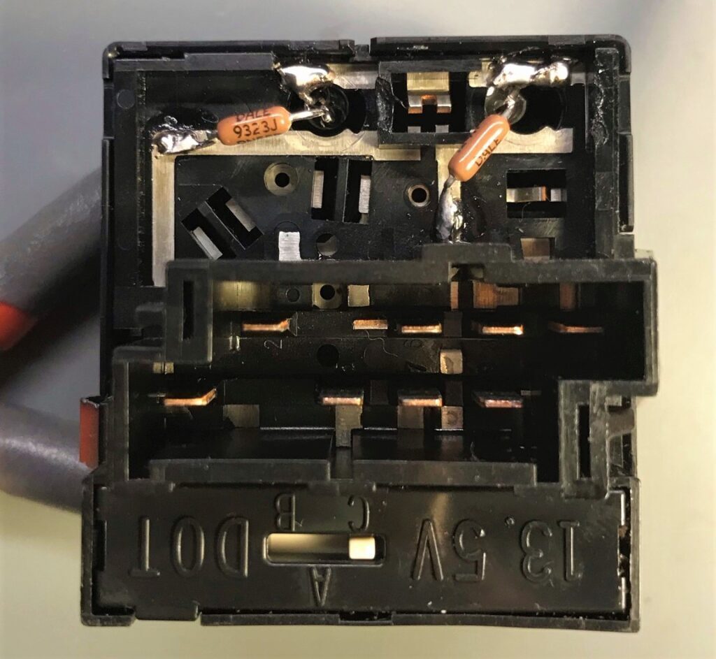
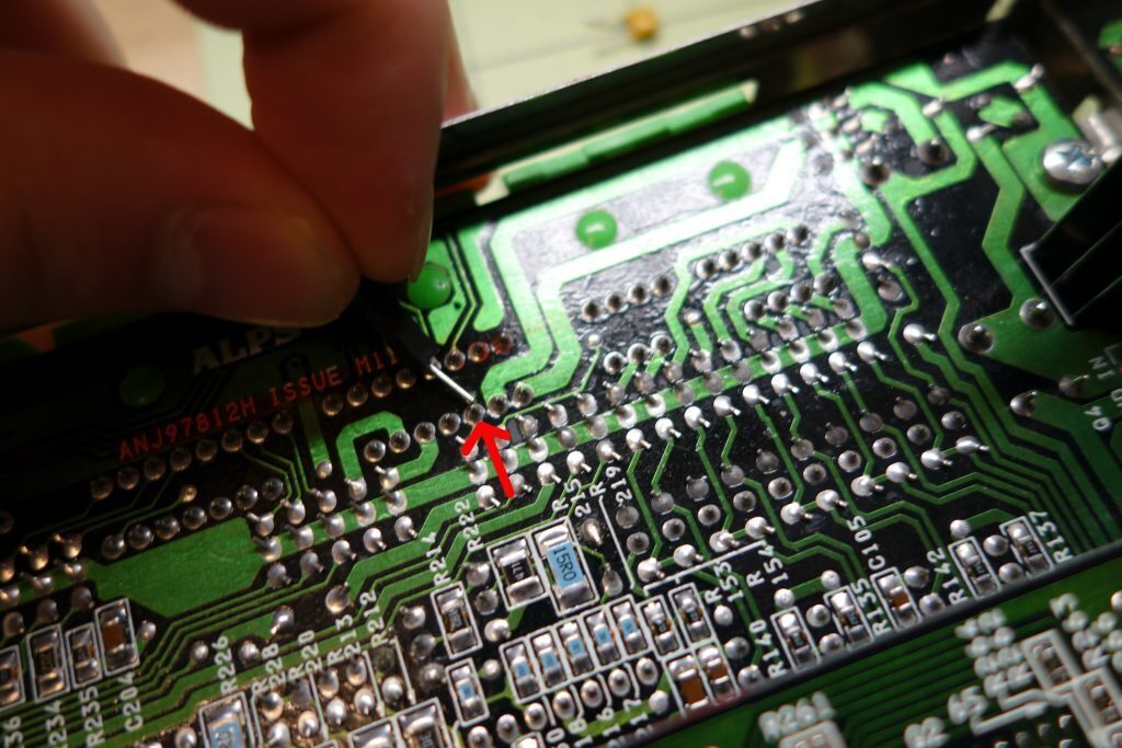
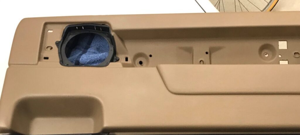
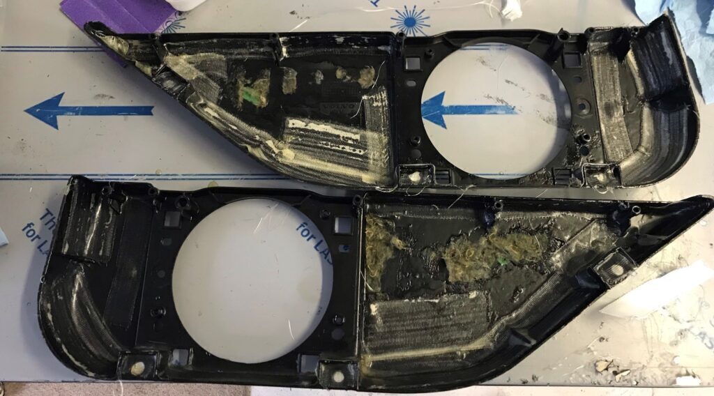
The First step is to cut out the old capacitor. Be careful doing this and make sure to leave as much of the existing leads as possible.
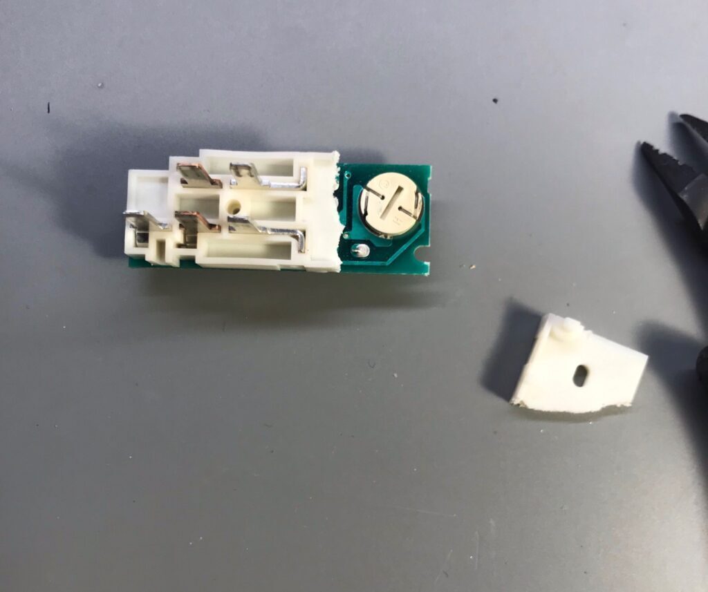
After removing the rear speakers, in some cases the plastic holding the tweeter may appear cracked or the plastic may begin to crack after reaching a tool in to cut the old capacitor out; later on we will reinforce these cracks with hot glue.
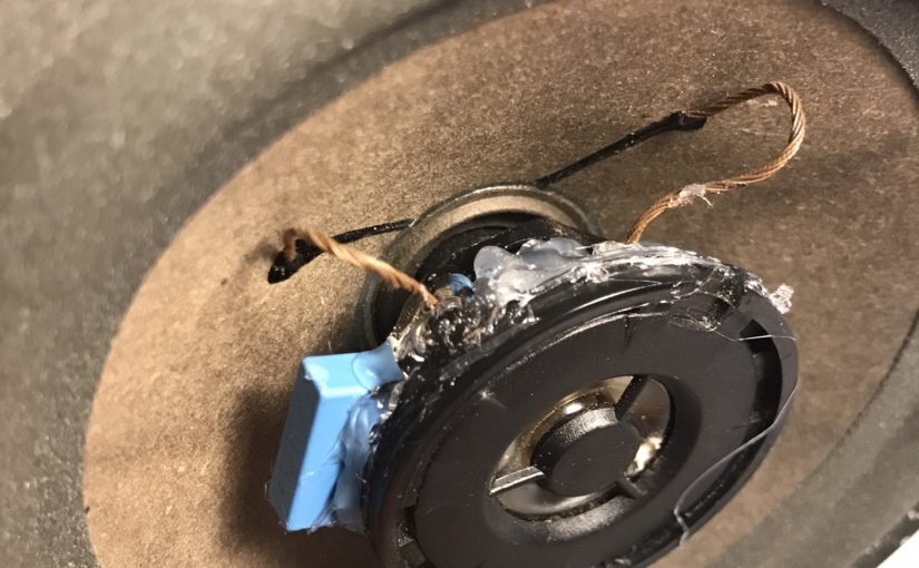
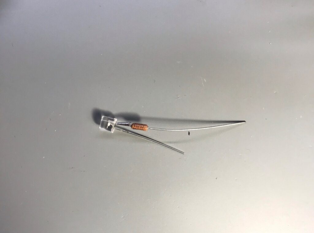
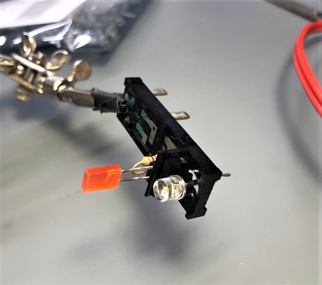
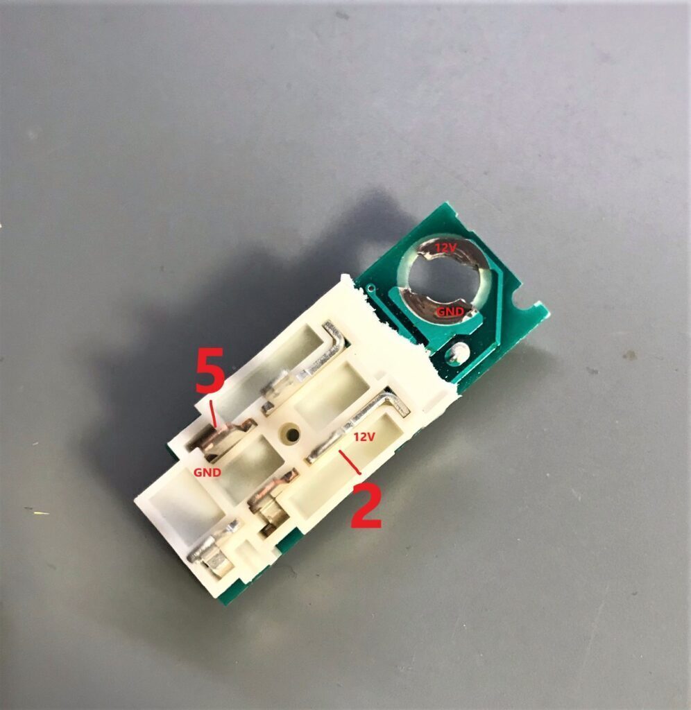
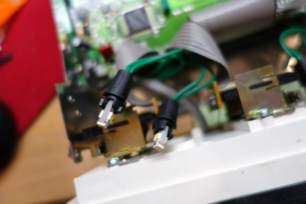
Now after selecting the new capacitor the pins need to be bent so that they can be soldered onto the existing leads of the tweeter.
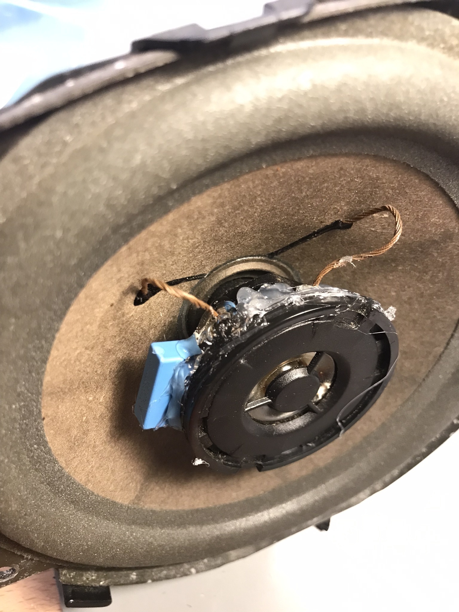
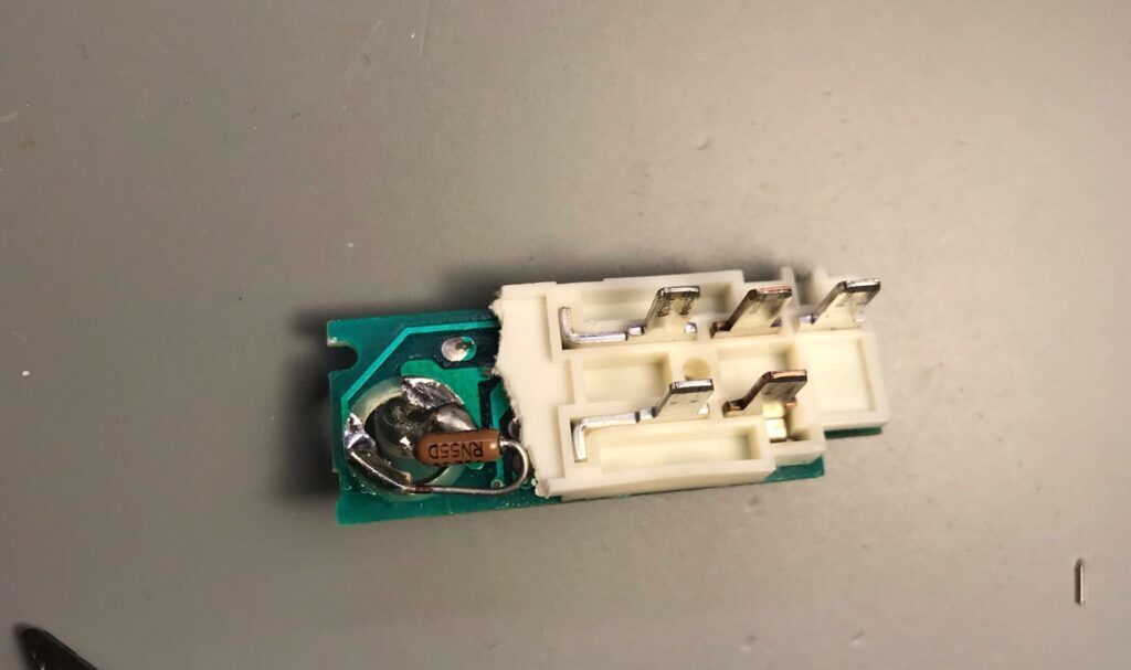
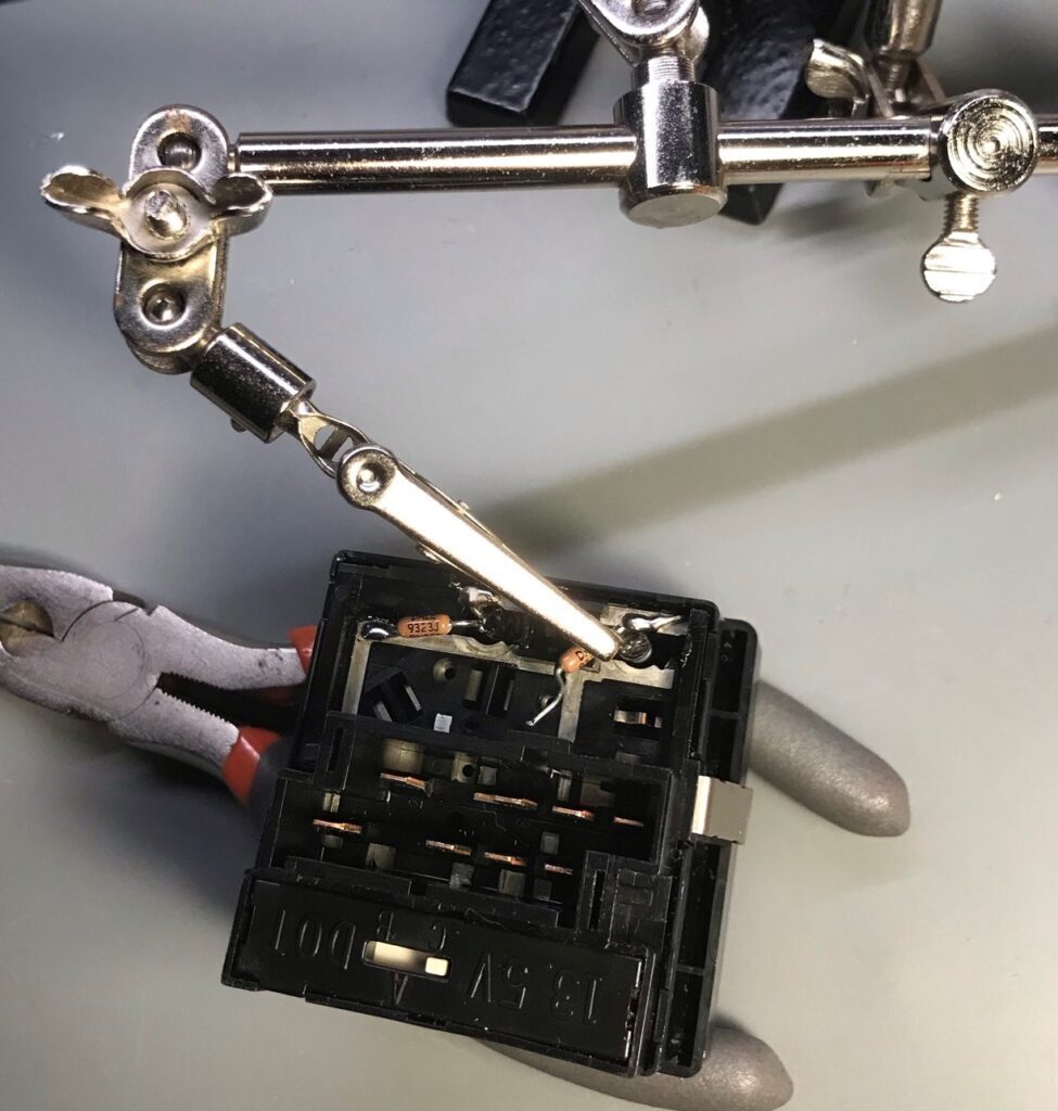
At this point, I tried holding the capacitor with helping hands but that did not allow enough room to get the soldering iron in. I found it best to hold the capacitor with my left hand and the soldering iron with my right hand. I simply tacked one of the leads (left photo) then moved on to the other lead. After the capacitor was in place, I cleaned up the solder.
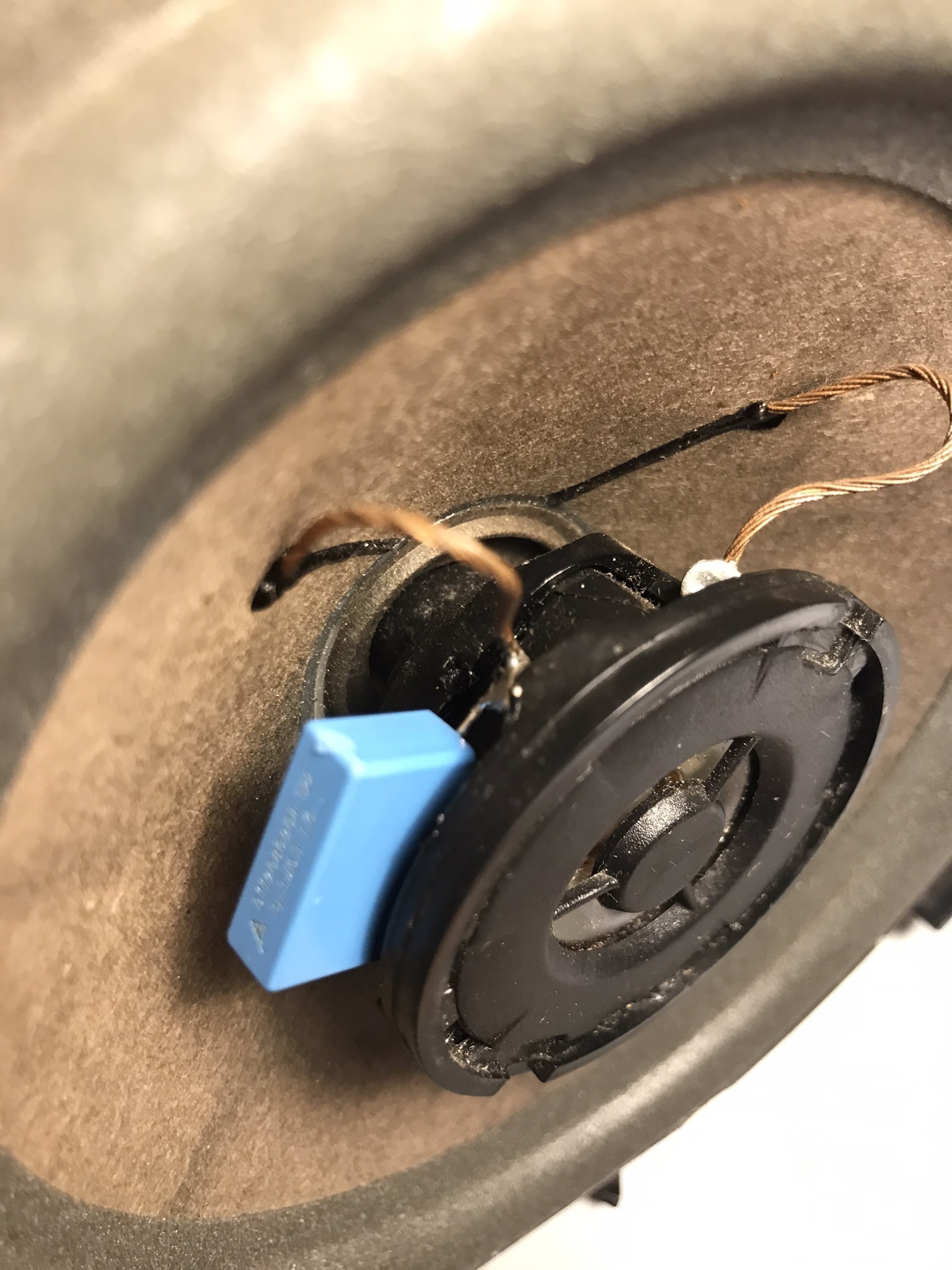
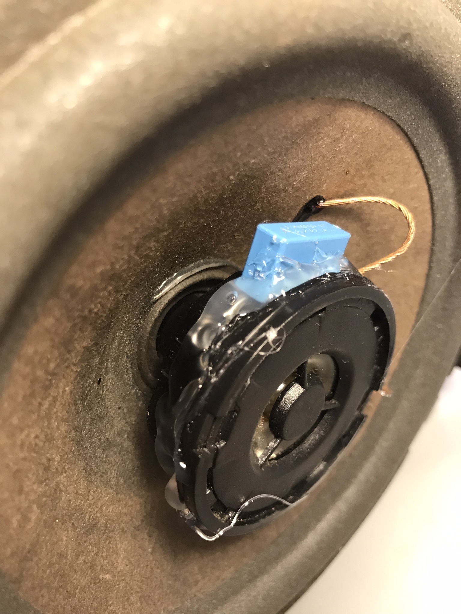
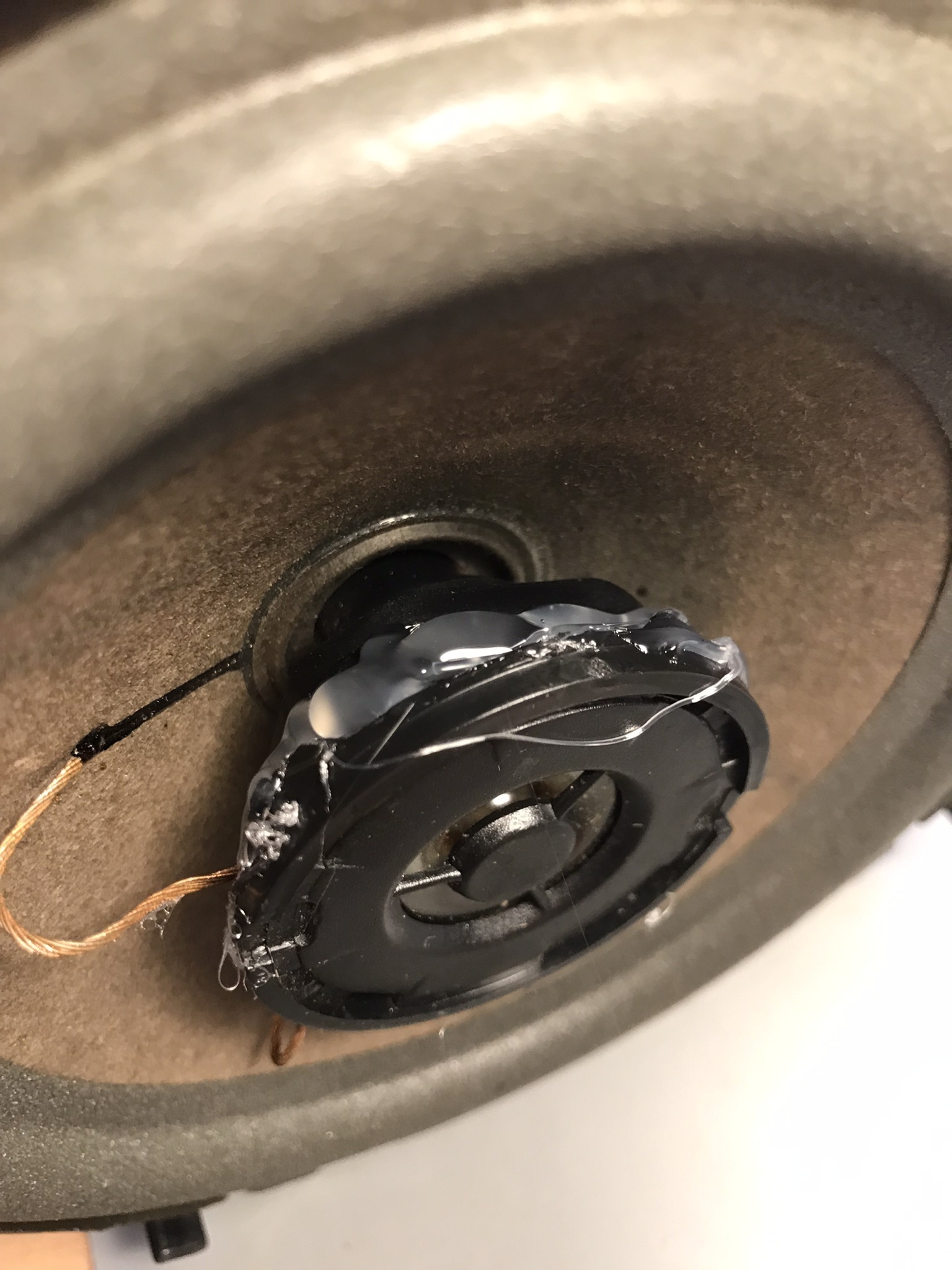
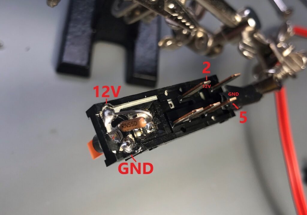
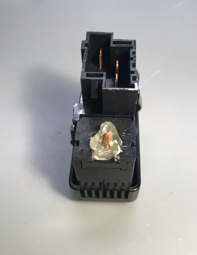
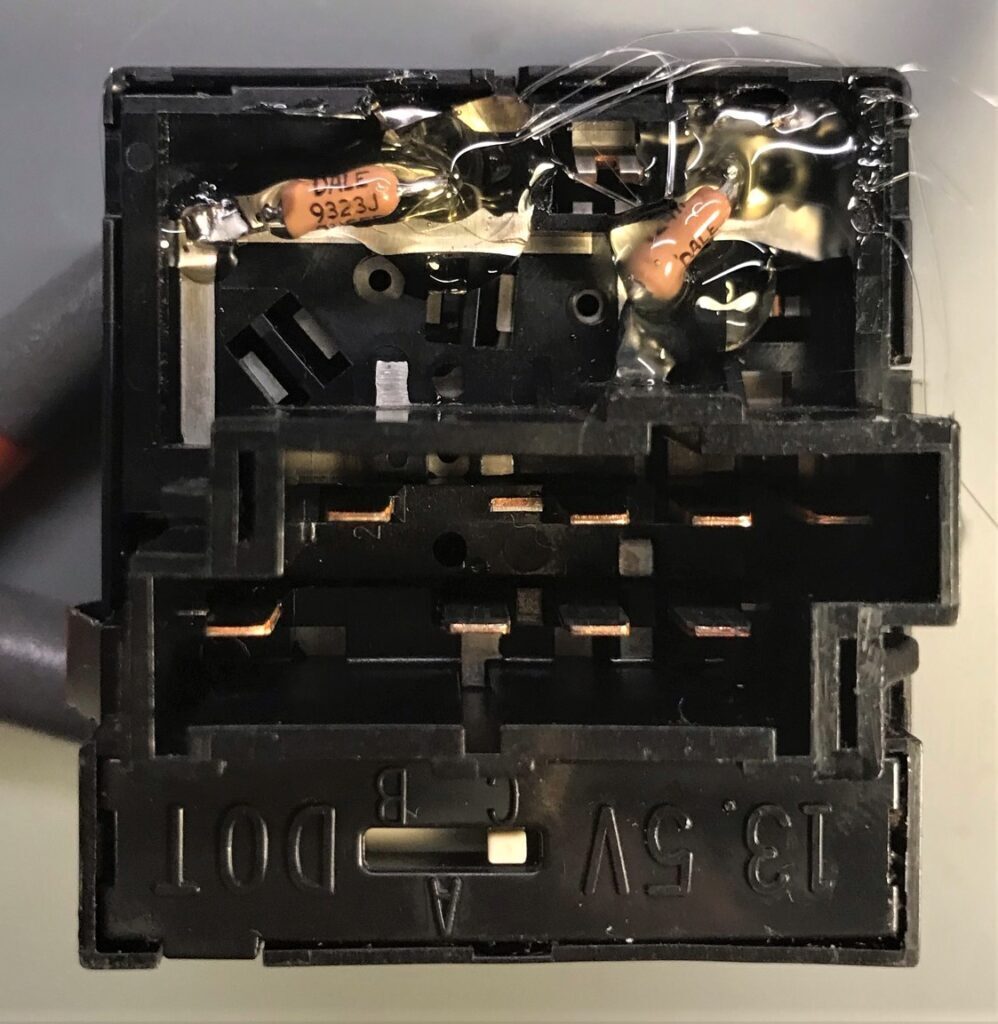
Lastly, I hot glued all around the tweeter housing. I also glued in the capacitor and its soldered leads to protect them from vibration.
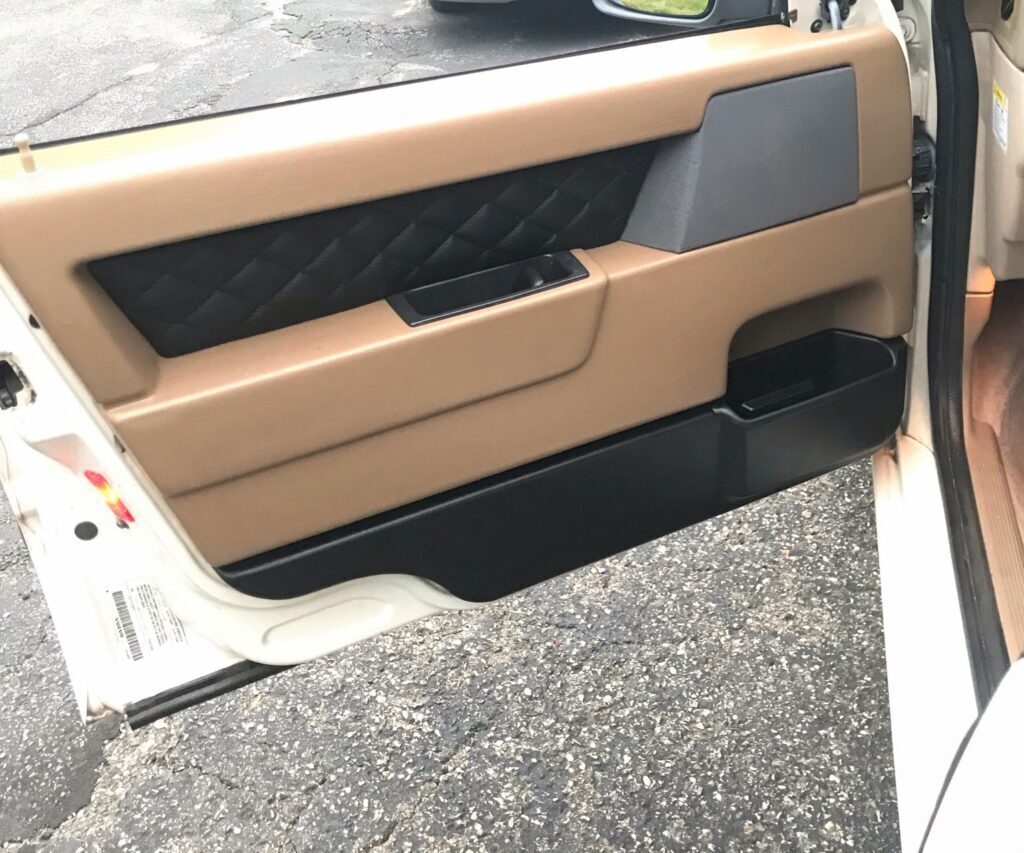
![[1997 Volvo 850] Door Panel Refurbishment](https://ryanbloomgren.com/wp-content/uploads/volvo850_doorpanel_finished-825x510.jpeg)

![[1997 Volvo 850] Recirculation motor replacement](https://ryanbloomgren.com/wp-content/uploads/volvo850_cc_recircmotor-825x510.jpeg)