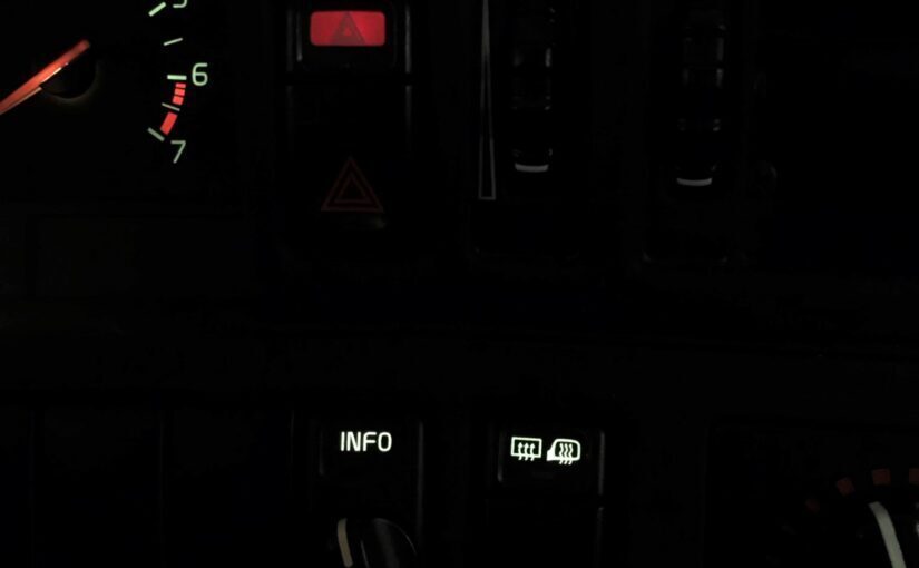
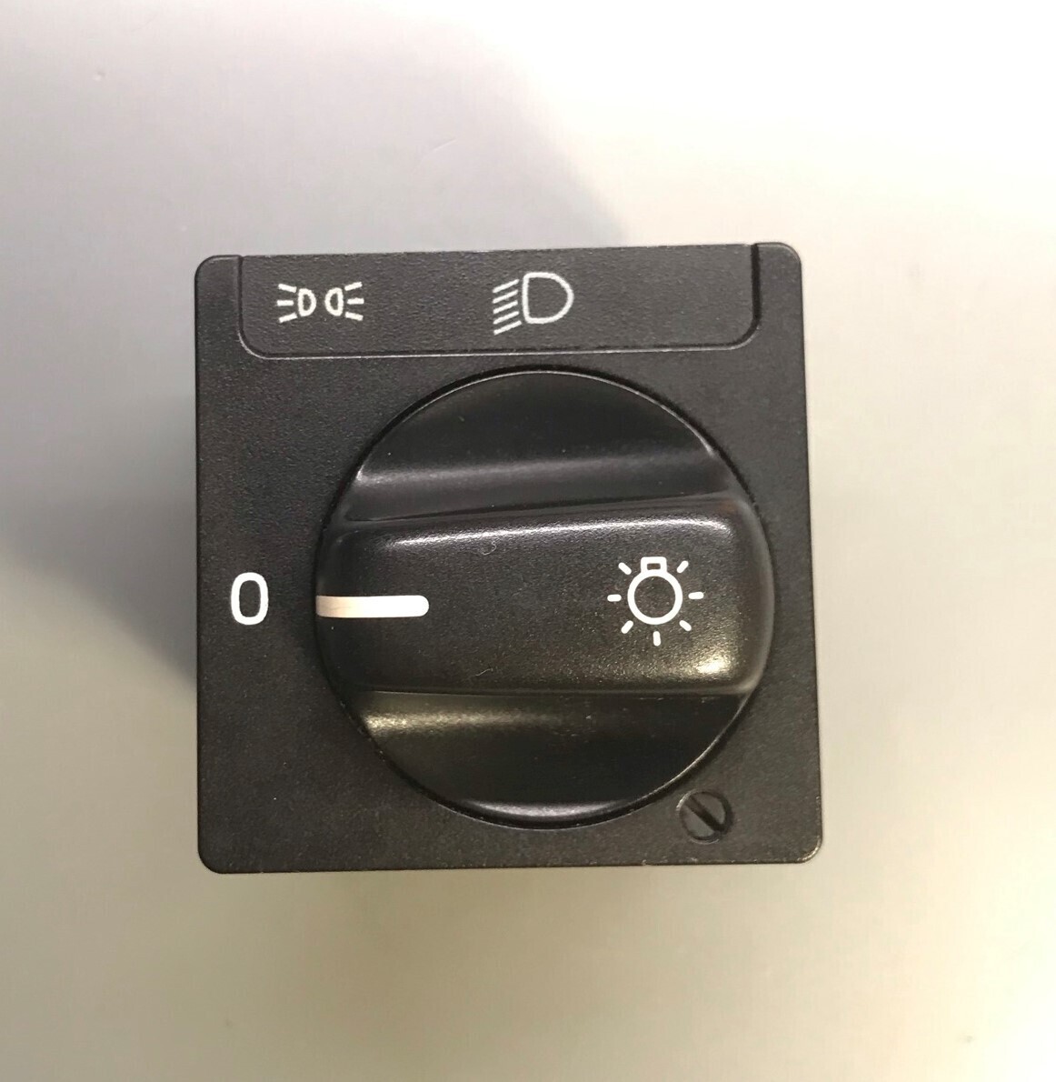
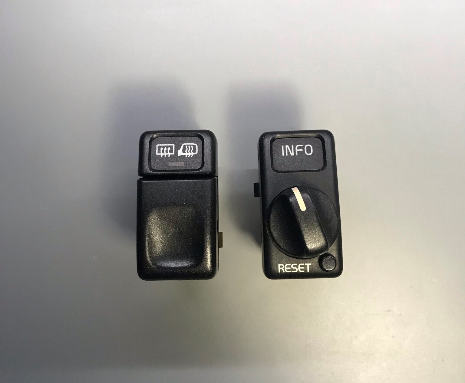
This tutorial shows how to replace the incandescent bulbs inside Volvo 850 switches with LEDs. This is applicable for all normal switches, the info switch, and the headlight switch.
Time:
Approx. 10 minutes a switch
What you’ll need:
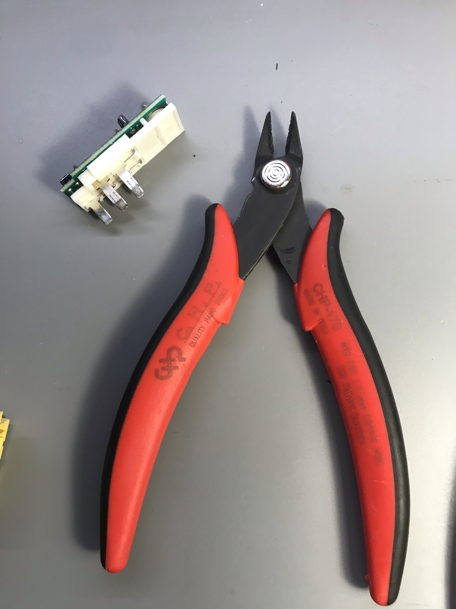
- Jewelers flat blade screwdrivers (the more the better)
- Warm white LED (5mm, Flat)
- Resistor (1.24K Ω) 1/4 watt [Calculated below for match]
- Hot Glue Gun
- Dielectric Grease (optional)
- Helping Hands Soldering Aid (optional)
– LED specs
Product Features: Warm White Lights / 5mm Flat Clear Lens Lens / 29mm Long Lead / DC 3.0V-3.2V (IF=20mA) / 0.06 Watts / Wavelength 2000K-3500K / 60° Viewing Angle
– Choosing a resistor value
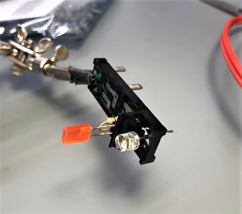
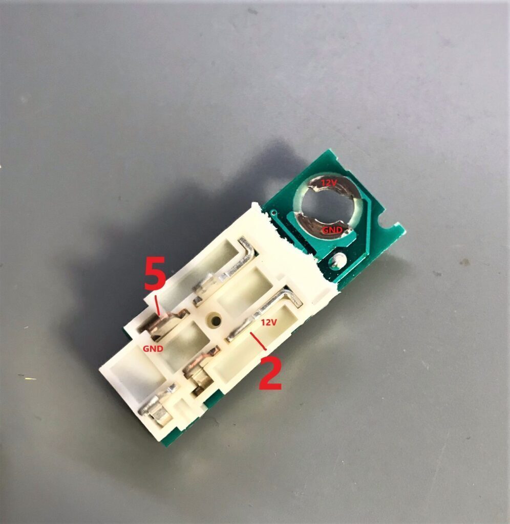
This step involves powering a non-LED converted switch on the bench from 12V and using another switch with the bulb removed from it so you can poke a LED through the back of it.
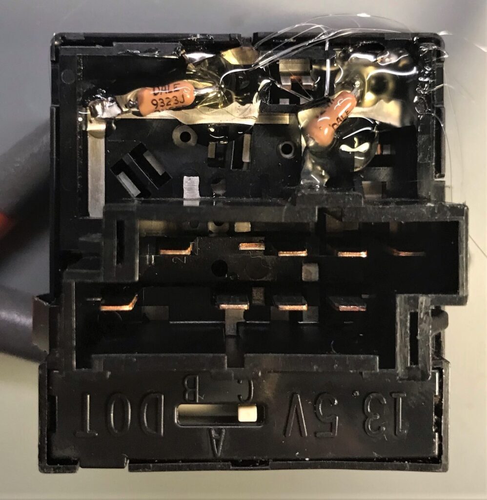
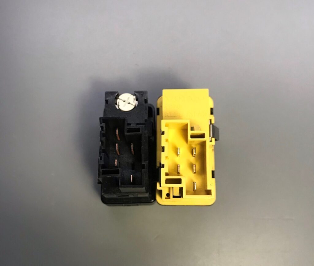
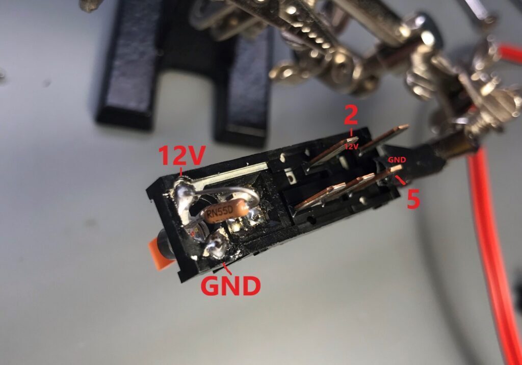
Pin 2 on the switch is 12V and Pin 5 is GND. These pin numbers are written next to the pins on the back of the switch.
Hook the LED up to a constant current power supply set at 12V so that you can dial in the appropriate current level so the LEDs match the lamps in the rest of the car. Make sure not to violate the maximum current of the LED!
Now with the LED on, take down the voltage that you read on the power supply (this is your LED forward voltage).
[ 12V – (LED FORWARD VOLTAGE) ] / Current (A) = Resistance (Ω)
For this tutorial, I will be using 1.24K Ω as a resistor value.
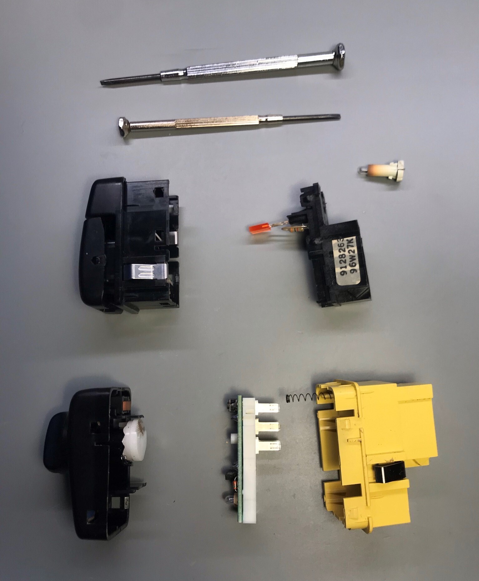
Preparation
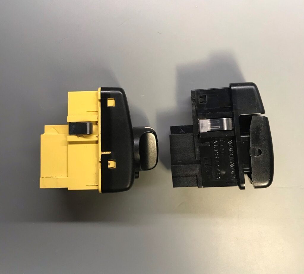
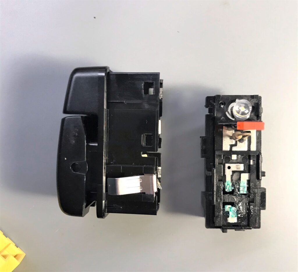
Start by opening up the switch by prying the tabs on all corners of the switch carefully and separating the face switch from the body (not necessary for headlight switch).
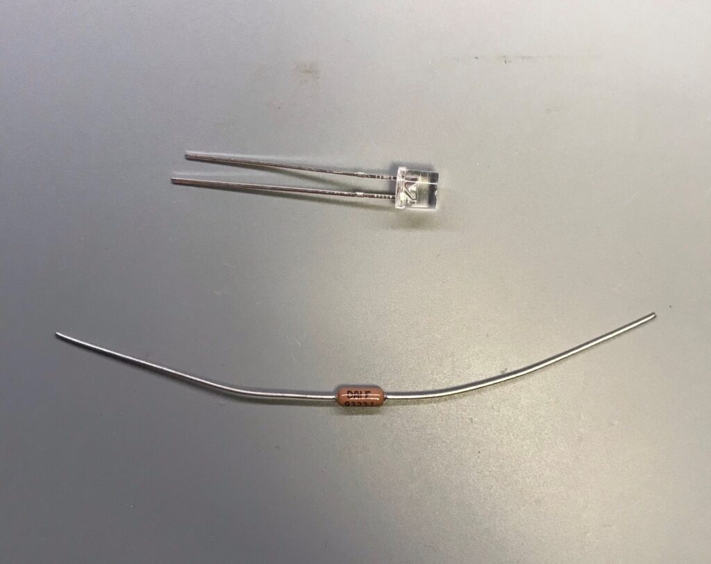
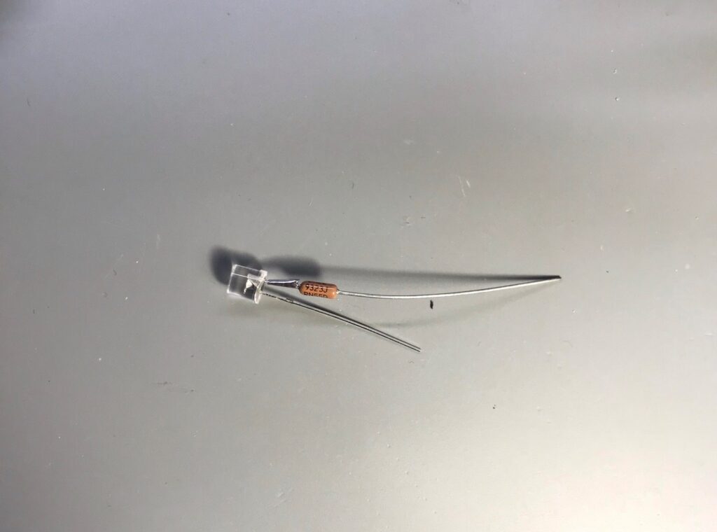
For the regular style switches it may be easier to solder the resistor to one leg of the LED (anode or positive side is used for this tutorial). Keep track which side of the LED has a flat spot on it (this is the negative side of the LED).
Regular Switch
Insert the LED into the switch. All you need to do is get the LED to be roughly aimed forward. The leg without the resistor can be soldered through a hole in the switch. The resistor can go through the “bulb hole”. Make sure the LED polarity matches the pictures below or there will be no light. You also want to make sure the resistor and LED leads don’t short out with how they are situated.
Now you can optionally clean the contacts and apply a dab of dielectric grease to protect the contacts before snapping the switch back together.
At this point the resistor is still hanging out the back. The simplest solution is to use some hot glue deep in the bulb hole to keep the LED and LED leads from moving. You can also use it to coat any bit of the resistor or resistor leads still sticking out the back.
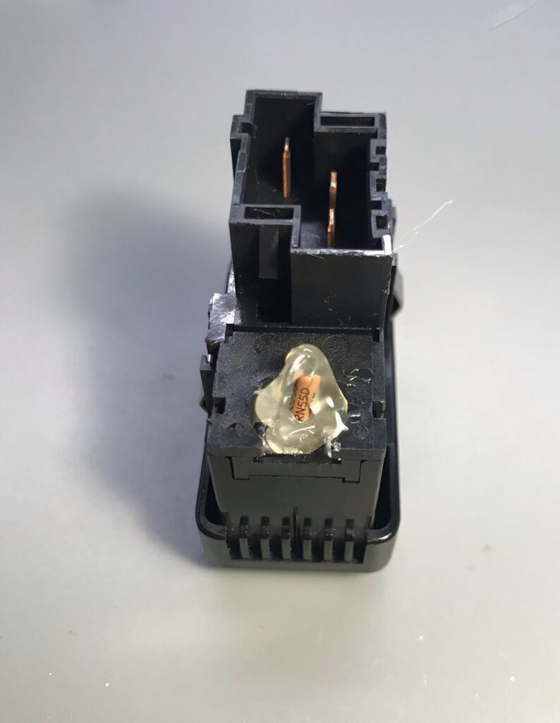
Info Switch
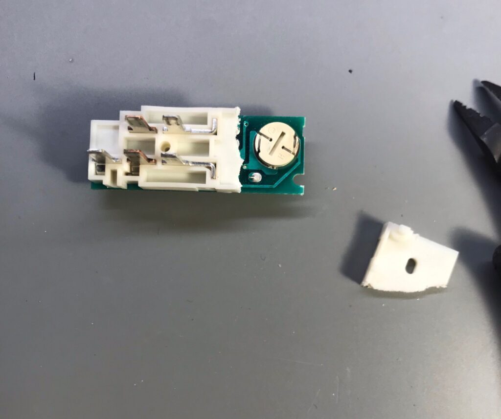
Once you get the switch open, to access the bulb, you must cut a bit of the white backing plastic.
I found it easier to solder the negative lead of the LED to the GND pad of the switch before soldering the resistor to the 12V leg.
You basically orient the LED as shown below. You may need to chop off a bit more white plastic. Make sure not to accidentally short any leads out.
The last step is to encase the LED and leads in hot glue. You can now optionally clean the tracks for the info switch on the front side of the PCB before reassembly.
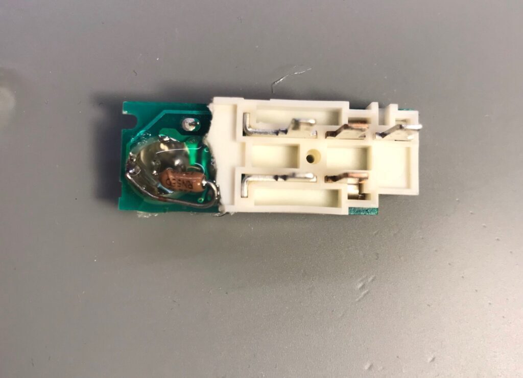
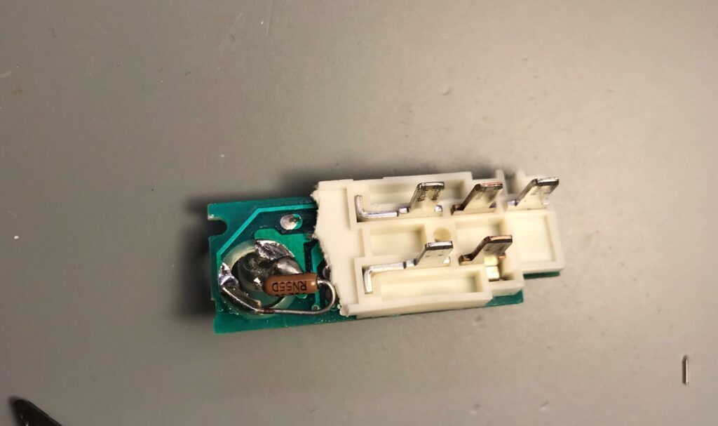
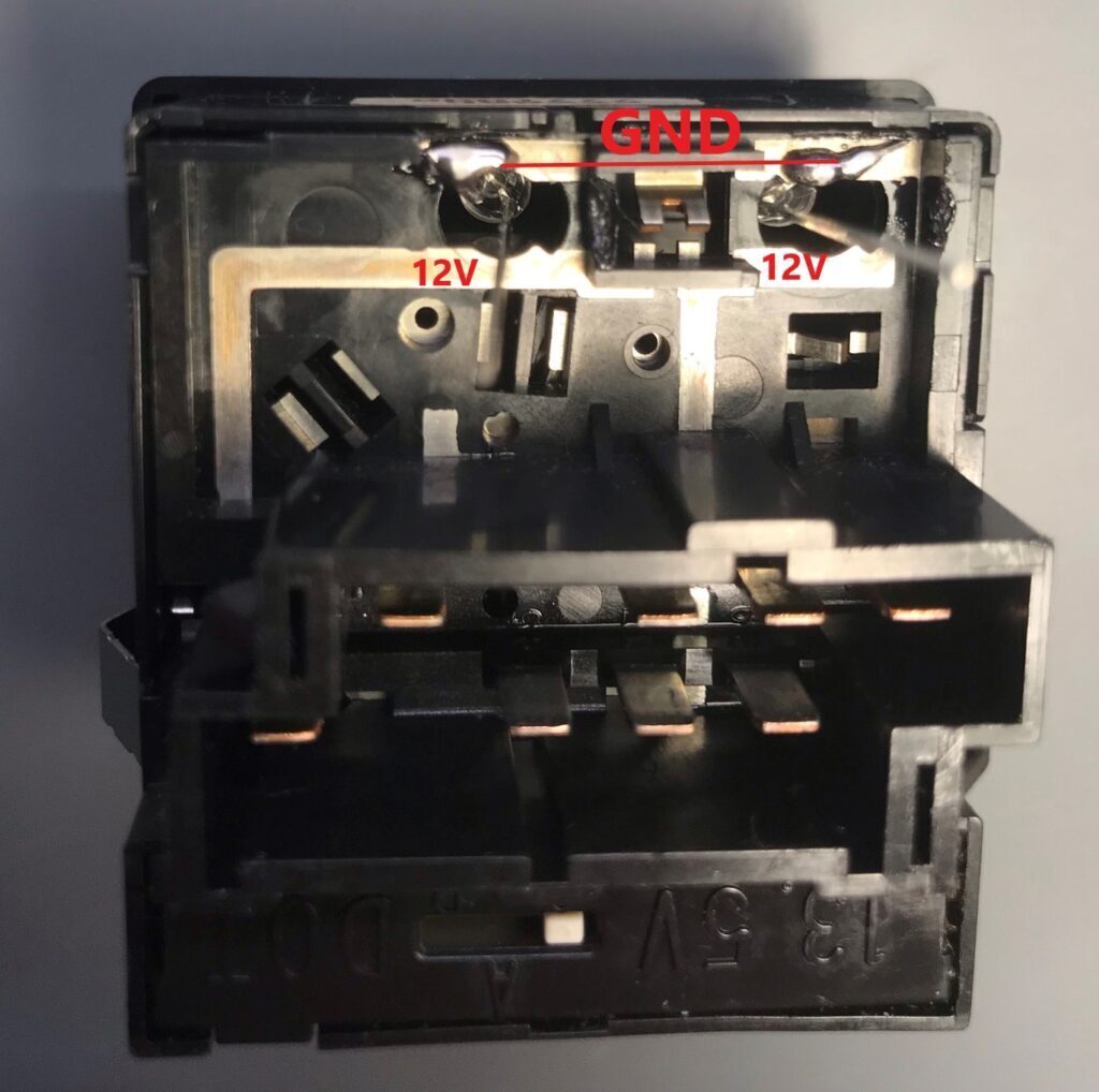
Headlight Switch
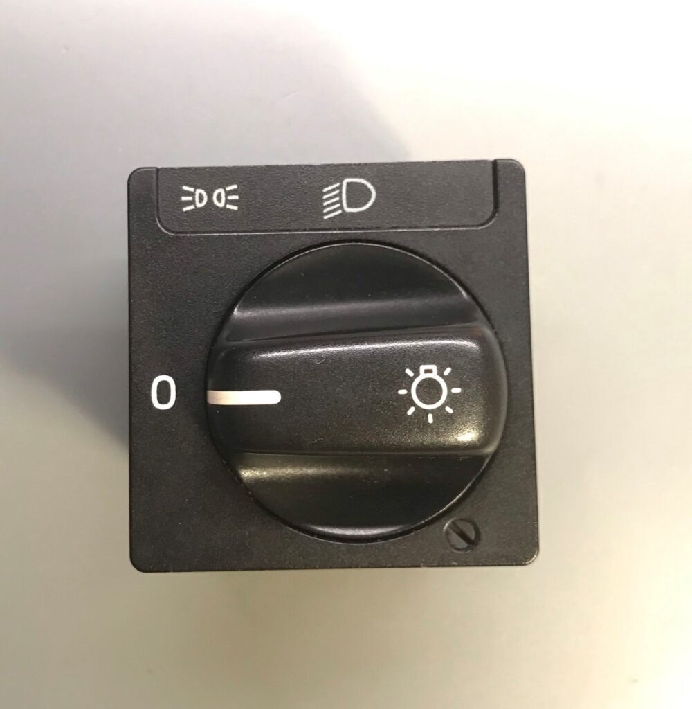
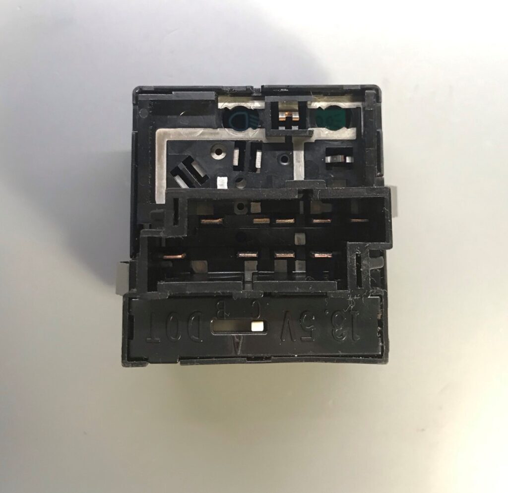
It is not necessary to open the headlight switch to install LEDs.
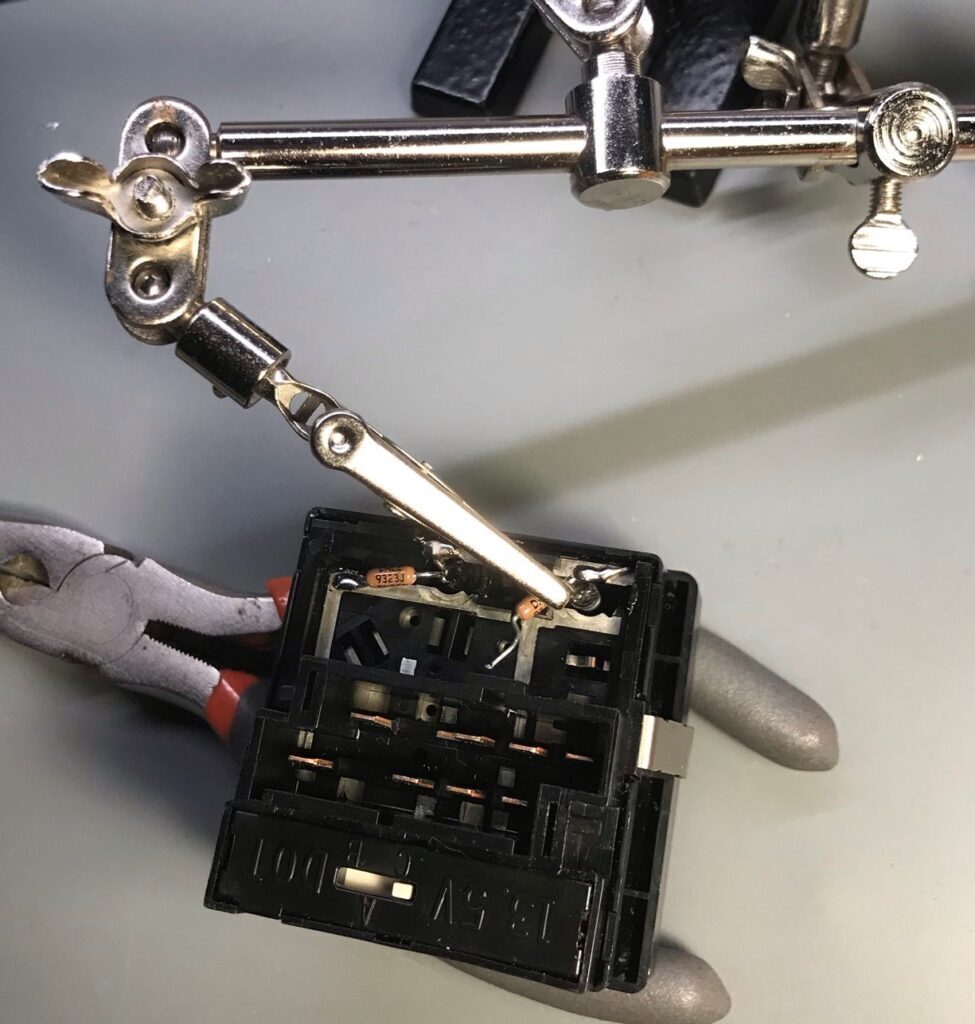
It was easy to use some helping hands to hold one leg of the LED to help solder the other bent leg of the LED. The LED cathode is soldered to the GND side.
You can use some helping hands to help hold the resistors for soldering.
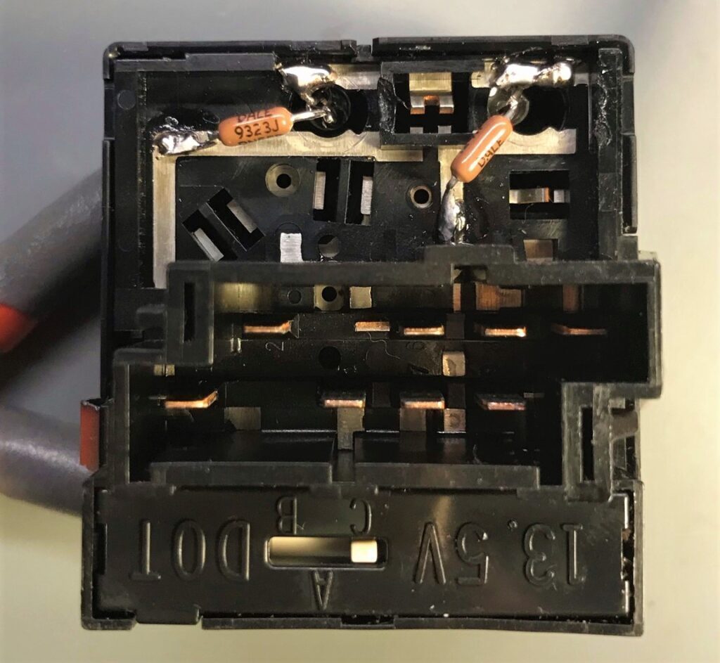
Make sure none of the leads are shorted. As a final step. I coat the back of the LED and resistor to avoid accidental shorts and vibration.